Nissan Frontier D22. Manual - part 200


  Index      Nissan     Nissan Frontier D22 Pickup (1998-2004 year) - Service and Repair Manual


Search            


Content   ..  198  199  200  201   ..


Nissan Frontier D22. Manual - part 200


REMOVAL AND INSTALLATION

BRC-131

[VDC/TCS/ABS]

C

D

E

G

H

I

J

K

L

M

A

B

BRC

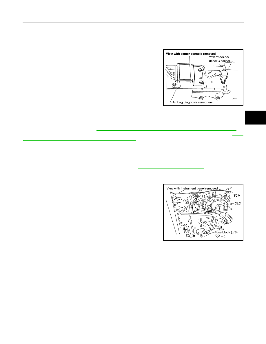
Yaw Rate/Side/Decel G Sensor

EFS003JB

Always replace sensor if bumped or dropped. Otherwise, performance characteristics of sensor will
be changed, which in turn changes ABS control performance characteristics.

CAUTION:

Do not exceed 9 N·m (0.9 kg-m, 80 in-lb) total tightening torque.

Steering Angle Sensor

EFS003JC

CAUTION:

The steering angle sensor must be adjusted after the spiral cable has been removed and reinstalled or
replaced with a new one. Refer to 

BRC-55, "Adjustment of Steering Angle Sensor Neutral Position"

 .

The steering angle sensor is built into the spiral cable. For removal and installation procedures, refer to 

SRS-

42, "DRIVER AIR BAG MODULE AND SPIRAL CABLE"

 .

CAN-LAN Converter (CLC)

EFS003JD

1.

Disconnect battery cable.

2.

Remove steering column cover.

3.

Remove instrument lower panel driver side. Refer to 

IP-10, "Removal and Installation"

 .

4.

Place ASCD control unit aside.

5.

Disconnect CLC harness connector.

6.

Remove bolt and then remove CLC.

Tightening torque:

Step 1

: 7 N·m (0.7 kg-m, 62 in-lb)

Step 2

: 9 N·m (0.9 kg-m, 80 in-lb)

LFIA0134E

LFIA0194E

BRC-132

[VDC/TCS/ABS]

REMOVAL AND INSTALLATION

CL-1

CLUTCH

C  TRANSMISSION/TRANSAXLE

CONTENTS

D

E

F

G

H

I

J

K

L

M

SECTION 

A

B

CL

PRECAUTIONS .......................................................... 2

Precautions .............................................................. 2

PREPARATION ........................................................... 3

Special Service Tools  ............................................... 3
Commercial Service Tools ........................................ 3

NOISE, VIBRATION, AND HARSHNESS (NVH) 
TROUBLESHOOTING ................................................ 4

NVH Troubleshooting Chart  ..................................... 4

CLUTCH SYSTEM — HYDRAULIC TYPE ................. 5

Components ............................................................. 5
Inspection and Adjustment ....................................... 6

CLUTCH PEDAL INSPECTION AND ADJUST-
MENT .................................................................... 6
BLEEDING PROCEDURE  .................................... 6

CLUTCH MASTER CYLINDER  .................................. 8

Components ............................................................. 8
Disassembly and Assembly  ..................................... 8
Inspection ................................................................. 8

OPERATING CYLINDER ............................................ 9

Components ............................................................. 9
Inspection ................................................................. 9

CLUTCH RELEASE MECHANISM ........................... 10

Components ........................................................... 10
Removal and Installation  ........................................ 10
Inspection ............................................................... 11
Lubrication .............................................................. 11

CLUTCH DISC, CLUTCH COVER AND FLYWHEEL ... 12

Components ........................................................... 12
Inspection and Adjustment  ..................................... 12

CLUTCH DISC  .................................................... 12
CLUTCH COVER AND FLYWHEEL  ................... 13
FLYWHEEL INSPECTION  .................................. 13

Installation .............................................................. 13

SERVICE DATA AND SPECIFICATIONS (SDS)  ...... 15

Clutch Control System ............................................ 15
Clutch Master Cylinder (with clutch damper) .......... 15
Clutch Operating Cylinder  ...................................... 15
Clutch Disc  ............................................................. 15
Clutch Cover ........................................................... 15
Clutch Pedal  ........................................................... 15

CL-2

PRECAUTIONS

PRECAUTIONS

PFP:00001

Precautions

ECS007GL

Recommended fluid is brake fluid “DOT 3”.

Never reuse drained brake fluid.

Be careful not to splash brake fluid on painted areas.

When removing and installing clutch piping, use Tool.

Use new brake fluid to clean or wash all parts of master cyl-
inder, operating cylinder and clutch damper.

Never use mineral oils such as gasoline or kerosene. It will
ruin the rubber parts of the hydraulic system.

WARNING:

After cleaning the clutch disc, wipe it with a dust collector. Do
not use compressed air.

SBR686C


Content   ..  198  199  200  201   ..