Nissan Frontier D22. Manual - part 175


  Index      Nissan     Nissan Frontier D22 Pickup (1998-2004 year) - Service and Repair Manual


Search            


Content   ..  173  174  175  176   ..


Nissan Frontier D22. Manual - part 175


TROUBLE DIAGNOSIS

BRC-31

[ABS]

C

D

E

G

H

I

J

K

L

M

A

B

BRC

–:Not applicable

ACTIVE TEST
Operation Procedure

CAUTION:

Do not perform active test while driving the vehicle.

Make sure to completely bleed air from brake system.

Active test cannot be performed when ABS warning lamp is on.

1.

Connect the CONSULT-II connector to the data link connector and start the engine.

CAUTION:

If CONSULT-II is used with no connection of CONSULT-II CONVERTER, malfunctions might be
detected in self-diagnosis depending on control unit which carry out CAN communication.

2.

Touch 

″START″ on the display.

3.

Touch 

″ABS″ and ″ACTIVE TEST″.
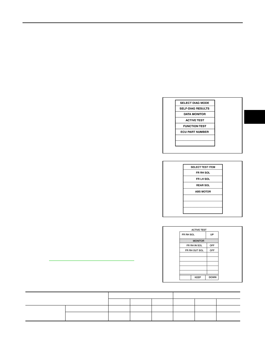
4.

Test item selection screen is displayed.

5.

Touch necessary test item.

6.

Touch 

″START″.

7.

Carry out the active test by touching screen key.

Solenoid Valve

1.

To perform active test of ABS functions, select major items for
each test item.

2.

For ABS solenoid valve, touch “UP”, “KEEP” and “DOWN”. For
ABS solenoid valve (ACT), touch “UP,”  “ACTUATOR UP” and
“ACTUATOR KEEP”. Use screen monitor to check that solenoid
valve operates as shown in Solenoid Valve Operation Chart.
Refer to 

BRC-88, "Solenoid Valve Operation Chart"

 .

Solenoid Valve Operation Chart

WFIA0043E

LBR379

LFIA0180E

Operation

ABS solenoid valve

ABS solenoid valve (ACT)

UP

KEEP

DOWN

UP

ACT UP

ACT KEEP

FR RH SOL
FR RH ABS SOLE-
NOID (ACT)

FR RH IN SOL

OFF

ON

ON

OFF

OFF

OFF

FR RH OUT SOL

OFF

OFF

ON*

OFF

OFF

OFF

BRC-32

[ABS]

TROUBLE DIAGNOSIS

*: ON for 1 to 2 seconds after the touch, and then OFF

NOTE:

If active test is performed with brake pedal depressed, pedal stroke may change. This is normal.

“TEST IS STOPPED” is displayed approximately 10 seconds after operation starts.

After “TEST IS STOPPED” is displayed, to perform test again, repeat Active Test Step 6.

ABS Motor

Touch “ON” and “OFF” on the screen. Check that ABS motor relay
operates as shown in table below.

NOTE:

If active test is performed with brake pedal depressed, pedal
stroke may change. This is normal.

“TEST IS STOPPED” is displayed approximately 10 seconds
after operation starts.

FR LH  SOL
FR LH ABS SOLE-
NOID (ACT)

FR LH IN SOL

OFF

ON

ON

OFF

OFF

OFF

FR LH OUT SOL

OFF

OFF

ON*

OFF

OFF

OFF

RR RH SOL
RR RH ABS SOLE-
NOID (ACT)

RR RH IN SOL

OFF

ON

ON

OFF

OFF

OFF

RR RH OUT SOL

OFF

OFF

ON*

OFF

OFF

OFF

RR LH  SOL
RR LH ABS SOLE-
NOID (ACT)

RR LH IN SOL

OFF

ON

ON

OFF

OFF

OFF

RR LH OUT SOL

OFF

OFF

ON*

OFF

OFF

OFF

Operation

ABS solenoid valve

ABS solenoid valve (ACT)

UP

KEEP

DOWN

UP

ACT UP

ACT KEEP

Operation

ON

OFF

ABS actuator relay

ON

ON

ABS motor relay

ON

OFF

SFIA0593E

TROUBLE DIAGNOSIS

BRC-33

[ABS]

C

D

E

G

H

I

J

K

L

M

A

B

BRC

For Fast and Accurate Diagnosis

EFS003GW

PRECAUTIONS FOR DIAGNOSIS

Before performing diagnosis, always read precautions. Refer to 

BRC-4, "PRECAUTIONS"

 .

When replacing ABS actuator and electric unit (control unit), be sure labels on control units are the same
color.

After diagnosis is finished, be sure to erase memory. Refer to 

BRC-26, "Operation Procedure"

 .

When checking continuity and voltage between units, be sure to check for disconnection, looseness,
bend, or collapse of connector terminals. If any non-standard condition is found, repair or replace connec-
tor terminals.

For intermittent symptoms, possible cause is malfunction in harness, harness connector, or terminals.
Move harness, harness connector, and terminals to check for poor connections.

If a circuit tester is used for the check, be careful not to forcibly extend any connector terminal.

To use CONSULT-II to perform self-diagnosis of ABS actuator and electric unit (control unit), active tests,
or work support, first stop work, then connect CONSULT-II and select “ABS”.

CONSULT-II self-diagnosis results are displayed without regard to occurrence timing. In some cases later
ones (timing value is small) appear on the next screen.

While self-diagnosis results of CONSULT-II shows an error, if CONSULT-II active test is performed, an
engine system error may be indicated. In this case, start engine to resume the normal screen.

The following symptoms may be caused by normal operations:

ON and OFF Timing for ABS Warning Lamp

×: ON

–: OFF

Symptom

Symptom description

Result

Motor operation noise

This is noise of motor inside ABS actuator. Slight noise may occur dur-
ing ABS operation.

Normal

When the vehicle speed goes over 20 km/h (12.5 mph), the motor and 
valves operating noise may be heard. It happens only once after IGN 
(ignition) is ON. This is a normal status of the system operation check.

System operation check 
noise

When the engine starts, slight “click” noise may be heard from engine 
compartment. This is normal and is part of system operation check.

Normal

ABS operation (Longer stop-
ping distance)

On roads with low friction coefficients, such as snowy roads or gravel 
roads, vehicles with ABS may require a longer stopping distance. There-
fore, when driving on such roads, avoid overconfidence and keep speed 
sufficiently low.

Normal

Condition

ABS warning lamp

Remarks

Ignition SW OFF

For approx. 2 seconds after ignition SW  is 
turned ON

×

Approx. 2 seconds after ignition switch ON

Turns OFF 2 seconds after ignition switch ON.

There is an ABS
error.

×

×

There is an ABS actuator and electric unit (control 
unit) error. (Power or ground malfunction)

BRC-34

[ABS]

TROUBLE DIAGNOSIS

Basic Inspection

EFS003GX

BASIC INSPECTION 1: BRAKE FLUID LEVEL AND LEAK INSPECTION

1.

Check fluid level in the brake reservoir tank. If fluid level is low, refill the brake fluid.

2.

Check for leakage in brake piping and around ABS actuator. If leakage or seepage is found, check as fol-
lows.

If ABS actuator and electric unit (control unit) connector is loose, tighten piping to specified torque.
Then inspect again and confirm that there is no leakage.

If connection of flare nuts or screws of ABS actuator are damaged, replace damaged parts. Then
inspect again and confirm that there is no leakage.

If there is leakage or seepage at any location other than ABS actuator connections, wipe away leakage
or seepage with clean cloth. Then inspect again and confirm that there is no leakage.

If there is leakage from ABS actuator, wipe away leakage or seepage with clean cloth. Then inspect
again. If there is leakage or seepage, replace ABS actuator unit.

CAUTION:

ABS actuator body cannot be disassembled.

3.

Check brake disc rotor and pads and brake drum and linings. Refer to 

MA-42, "Checking Disc Brake"

  and

MA-42, "Checking Drum Brake"

 .

BASIC INSPECTION 2: INSPECTION FOR LOOSENESS OF POWER SYSTEM TERMINALS

Check battery for looseness on the battery positive/negative terminals and ground connection. If looseness is
detected, tighten the cables to the specified torque. Check that the battery voltage does not drop and the gen-
erator is normal.

BASIC INSPECTION 3: INSPECTION OF ABS WARNING LAMP

1.

Check that ABS warning lamp illuminates for approximately 2 seconds when ignition switch is turned ON.
If it does not illuminate, inspect ABS warning lamp and circuit, and inspect combination meter. Refer to

BRC-13, "Schematic"

 .

Symptom Chart

EFS003GY

Symptom

Malfunctioning part

Reference 

page

ABS works frequently

BRC-44

Unexpected pedal reaction

BRC-44

Long stopping distance

BRC-45

ABS does not work

BRC-46

Pedal vibration and noise

BRC-46

ABS warning lamp does not illuminate

Fuse

Combination meter

Circuit(s)

ABS actuator and electric unit (control unit)

BRC-42


Content   ..  173  174  175  176   ..