Nissan Frontier D22. Manual - part 146
POWER DOOR LOCK SYSTEM
BL-21
C
D
E
F
G
H
J
K
L
M
A
B
BL
2.
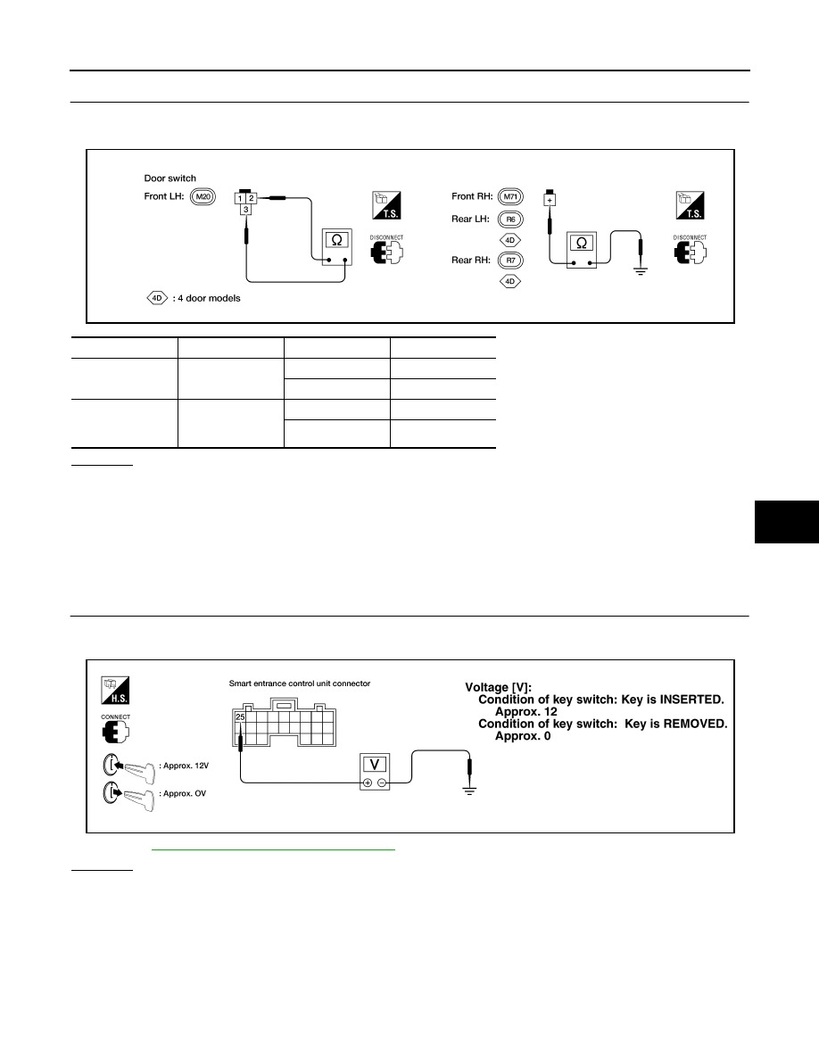
CHECK FRONT DOOR SWITCH
1.
Disconnect door switch harness connector.
2.
Check continuity between door switch terminals.
OK or NG
OK
>> Check the following
●
Front door switch LH ground circuit or front door switch RH ground condition
●
Harness for open or short between smart entrance control unit and door switch
NG
>> Replace door switch.
KEY SWITCH (INSERTED) CHECK
1.
CHECK KEY SWITCH INPUT SIGNAL
1.
Check voltage between smart entrance control unit harness connector M111 terminal 25 (W/G) and
ground.
2.
BL-16, "Wiring Diagram — D/LOCK —"
OK or NG
OK
>> Key switch is OK.
NG
>> GO TO 2.
Terminals
Condition
Continuity
Front door switch
LH
2 - 3
Closed
No
Open
Yes
Front door switch
RH and rear door
switches
(+) - Ground
Closed
No
Open
Yes
AEL577C
LEL010A