Nissan Frontier D22. Manual - part 133
SERVICE DATA AND SPECIFICATIONS (SDS)
AT-501
[RE4R01A]
D
E
F
G
H
I
J
K
L
M
A
B
AT
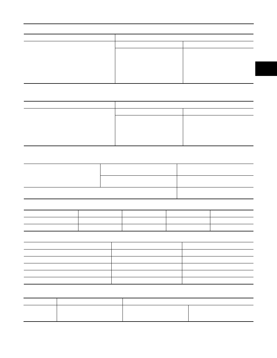
Total End Play
ECS007QU
*: Always check with the Parts Department for the latest parts information.
Reverse Clutch Drum End Play
ECS007QV
*: Always check with the Parts Department for the latest parts information.
Removal and Installation
ECS007QW
Shift Solenoid Valves
ECS007QX
Solenoid Valves
ECS007QY
A/T Fluid Temperature Sensor
ECS007QZ
Remarks: Specification data are reference values.
Total end play “T
1
”
0.25 - 0.55 mm (0.0098 - 0.0217 in)
Thickness of oil pump cover bearing race
Thickness mm (in)
Part No.*
0.8 (0.031)
1.0 (0.039)
1.2 (0.047)
1.4 (0.055)
1.6 (0.063)
1.8 (0.071)
2.0 (0.079)
31435-41X01
31435-41X02
31435-41X03
31435-41X04
31435-41X05
31435-41X06
31435-41X07
Reverse clutch drum end play “T
2
”
0.55 - 0.90 mm (0.0217 - 0.0354 in)
Thickness of oil pump thrust washer
Thickness mm (in)
Part No.*
0.9 (0.035)
1.1 (0.043)
1.3 (0.051)
1.5 (0.059)
1.7 (0.067)
1.9 (0.075)
31528-21X01
31528-21X02
31528-21X03
31528-21X04
31528-21X05
31528-21X06
Manual control linkage
Number of returning revolutions for lock
nut
2
Lock nut tightening torque
4.4 - 5.9 N·m (0.45 - 0.60 kg-m, 39.1 - 52.1
in-lb)
Distance between end of clutch housing and torque converter
26.0 mm (1.024 in) or more (VG33E only)
25.0 mm (0.984 in) or more (VG33ER only)
Gear position
1
2
3
4
Shift solenoid valve A
ON (Closed)
OFF (Open)
OFF (Open)
ON (Closed)
Shift solenoid valve B
ON (Closed)
ON (Closed)
OFF (Open)
OFF (Open)
Solenoid valves
Resistance (Approx.)
Ω
Terminal No.
Shift solenoid valve A
20 - 40
3
Shift solenoid valve B
20 - 40
2
Overrun clutch solenoid valve
20 - 40
4
Line pressure solenoid valve
2.5 - 5
6
Torque converter clutch solenoid valve
10 - 20
7
Monitor item
Condition
Specification (Approx.)
A/T fluid temper-
ature sensor
Cold [20
°C (68°F)]
↓
Hot [80
°C (176°F)]
1.5V
↓
0.5V
2.5 k
Ω
↓
0.3 k
Ω