Nissan Frontier D22. Manual - part 115


  Index      Nissan     Nissan Frontier D22 Pickup (1998-2004 year) - Service and Repair Manual


Search            


Content   ..  113  114  115  116   ..


Nissan Frontier D22. Manual - part 115


OIL PUMP

AT-429

[RE4R01A]

D

E

F

G

H

I

J

K

L

M

A

B

AT

2.

Install cam ring in oil pump housing as follows:

a.

Install side seal on control piston.

Pay attention to its direction — Black surface goes
toward control piston.

Apply petroleum jelly to side seal.

b.

Install control piston on oil pump.

c.

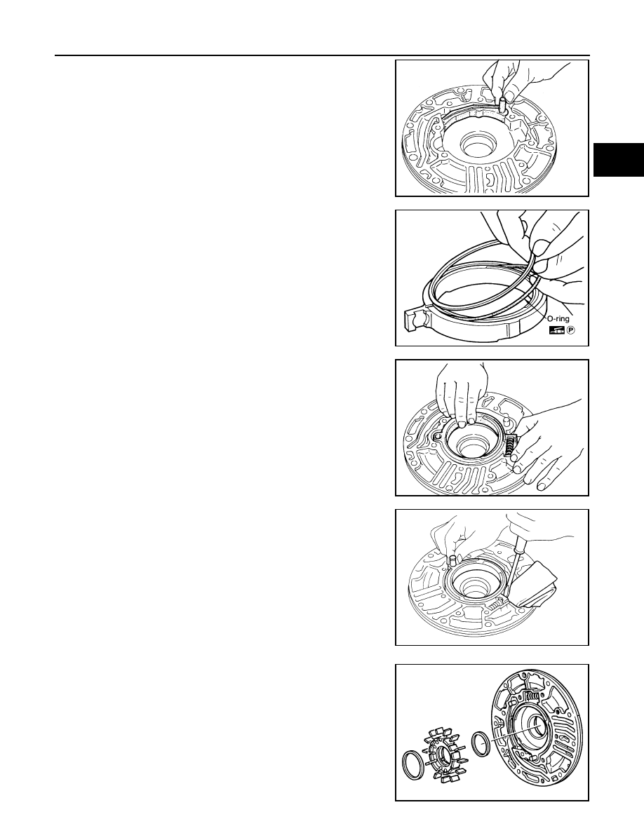
Install O-ring and friction ring on cam ring.

Apply petroleum jelly to O-ring.

d.

Assemble cam ring, cam ring spring and spring seat. Install
spring by pushing it against pump housing.

e.

While pushing on cam ring install pivot pin.

3.

Install rotor, vanes and vane rings.

Pay attention to direction of rotor.

SAT654A

SAT660A

SAT661A

SAT651A

SAT662A

AT-430

[RE4R01A]

OIL PUMP

4.

Install oil pump housing and oil pump cover.

a.

Wrap masking tape around splines of oil pump cover assembly
to protect seal. Position oil pump cover assembly in oil pump
housing assembly, then remove masking tape.

b.

Tighten bolts in a crisscross pattern.

5.

Install new seal rings carefully after packing ring grooves with
petroleum jelly. Press rings down into jelly to a close fit.

Seal rings come in two different diameters. Check fit care-
fully in each groove.

Do not spread gap of seal ring excessively while installing.
It may deform ring.

SAT649A

Small dia. seal ring

: No mark

Large dia. seal ring

: Yellow mark in area 
shown by arrow

SAT663A

CONTROL VALVE ASSEMBLY

AT-431

[RE4R01A]

D

E

F

G

H

I

J

K

L

M

A

B

AT

CONTROL VALVE ASSEMBLY

PFP:31705

Components

ECS007PG

LCIA0275E

AT-432

[RE4R01A]

CONTROL VALVE ASSEMBLY

Disassembly

ECS007PH

1.

Remove solenoids.

a.

Remove torque converter clutch solenoid valve and side plate
from lower body.

b.

Remove O-ring from solenoid.

c.

Remove line pressure solenoid valve from upper body.

d.

Remove O-ring from solenoid.

e.

Remove 3-unit solenoid assembly from upper body.

f.

Remove O-rings from solenoids.

2.

Disassemble upper and lower bodies.

a.

Place upper body face down, and remove bolts, reamer bolts,
side plate and support plates.

b.

Remove lower body and separator plate as a unit from upper
body.

Be careful not to drop pilot filter, orifice check valve,
spring and steel balls.

SAT194B

SAT667A

SAT043G

SAT195B


Content   ..  113  114  115  116   ..