Nissan Frontier D22. Manual - part 29


  Index      Nissan     Nissan Frontier D22 Pickup (1998-2004 year) - Service and Repair Manual


Search            


Content   ..  27  28  29  30   ..


Nissan Frontier D22. Manual - part 29


OIL PUMP

AT-85

[RL4R01A]

D

E

F

G

H

I

J

K

L

M

A

B

AT

7.

Remove oil seal from oil pump housing.

Be careful not to scratch oil pump housing.

Inspection

ECS007JJ

OIL PUMP COVER, ROTOR, VANES, CONTROL PISTON, SIDE SEALS, CAM RING AND FRIC-
TION RING

Check for wear and damage.
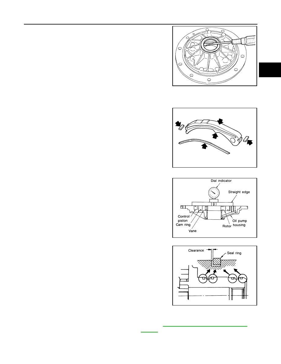
SIDE CLEARANCES

Measure side clearances between end of oil pump housing and
cam ring, rotor, vanes and control piston in at least four places
along their circumferences. Maximum measured values should
be within specified ranges.

Before measuring side clearance, check that friction rings, O-ring, control piston side seals and
cam ring return spring are removed.

If not within standard clearance, replace oil pump assembly except oil pump cover assembly.

SAT655A

SAT656A

SAT657A

SAT658A

Standard clearance (Cam ring, rotor, 
vanes and control piston)

: Refer to 

AT-154, "Oil Pump and Low One-way 

Clutch"

 .

AT-86

[RL4R01A]

OIL PUMP

SEAL RING CLEARANCE

Measure clearance between seal ring and ring groove.

If not within wear limit, replace oil pump cover assembly.

Assembly

ECS007JK

1.

Drive oil seal into oil pump housing.

Apply ATF to outer periphery and lip surface.

2.

Install cam ring in oil pump housing as follows:

a.

Install side seal on control piston.

Pay attention to its direction — black surface faces
toward control piston.

Apply petroleum jelly to side seal.

b.

Install control piston on oil pump.

c.

Install O-ring and friction ring on cam ring.

Apply petroleum jelly to O-ring.

d.

Assemble cam ring, cam ring return spring and spring seat.
Install spring by pushing it against pump housing.

Standard clearance

: 0.10 - 0.25 mm (0.0039 - 
0.0098 in)

Wear limit

: 0.25 mm (0.0098 in)

SAT081E

SAT654A

SAT660A

SAT661A

OIL PUMP

AT-87

[RL4R01A]

D

E

F

G

H

I

J

K

L

M

A

B

AT

e.

While pushing on cam ring, install pivot pin.

3.

Install rotor, vanes and vane rings.

Pay attention to direction of rotor.

4.

Install oil pump housing and oil pump cover.

a.

Wrap masking tape around splines of oil pump cover assembly
to protect seal. Position oil pump cover assembly in oil pump
housing assembly, then remove masking tape.

b.

Tighten bolts in numerical order as shown.

5.

Install seal rings carefully after packing ring grooves with petro-
leum jelly. Press rings down into jelly for a close fit.

Seal rings come in two different diameters. Check fit
carefully in each groove.

Do not spread gap of seal ring excessively while install-
ing. It may deform ring.

SAT651A

SAT662A

SAT649A

Small dia. seal ring

: No mark

Large dia. seal ring

: Yellow mark in area 
shown by arrow

SAT663A

AT-88

[RL4R01A]

CONTROL VALVE ASSEMBLY

CONTROL VALVE ASSEMBLY

PFP:31705

Components

ECS007JL

LCIA0281E


Content   ..  27  28  29  30   ..