Nissan Xterra. Manual - part 739


  Index      Nissan     Nissan Xterra (2014 year) - Service and Repair Manual


Search            


Content   ..  737  738  739  740   ..


Nissan Xterra. Manual - part 739


FRONT WIPER DOES NOT OPERATE

WW-65

< SYMPTOM DIAGNOSIS >

C

D

E

F

G

H

I

J

K

M

A

B

WW

N

O

P

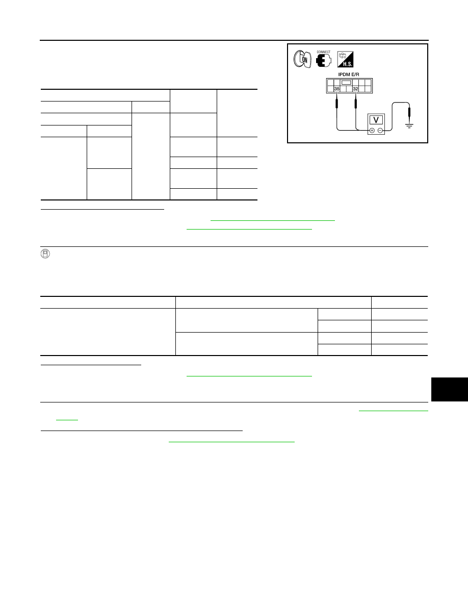
1. Turn the ignition switch ON.

2. Select "FRONT WIPER" of IPDM E/R active test item.

3. With operating the test item, check voltage between IPDM E/R

harness connector and ground.

Is the measurement value normal?

YES

>> Replace front wiper motor. Refer to 

WW-68, "Removal and Installation"

.

NO

>> Replace IPDM E/R. Refer to 

PCS-27, "Removal and Installation"

.

5.

 CHECK FRONT WIPER REQUEST SIGNAL INPUT

CONSULT DATA MONITOR

1. Select "FR WIP REQ" of IPDM E/R data monitor item.

2. Switch the front wiper switch to HI and LO.

3. With operating the front wiper switch, check the status of "FR WIP REQ".

Is the status of item normal?

YES

>> Replace IPDM E/R. Refer to 

PCS-27, "Removal and Installation"

.

NO

>> GO TO 6

6.

 CHECK COMBINATION SWITCH (WIPER AND WASHER SWITCH)

1. Perform the inspection of the combination switch (wiper and washer switch). Refer to 

BCS-48, "Symptom

Table"

.

Is combination switch (wiper and washer switch) normal?

YES

>> Replace BCM. Refer to 

BCS-50, "Removal and Installation"

.

NO

>> Repair or replace the affected parts.

Terminals

Test item

Voltage 

(Approx.)

(+)

(

−)

IPDM E/R

Ground

FRONT WIP-

ER

Connector

Terminal

E121

32

LO

Battery 
voltage

OFF

0 V

35

HI

Battery 
voltage

OFF

0 V

WKIA1427E

Monitor item

Condition

Monitor status

FR WIP REQ

Front wiper switch HI

HI

ON

STOP

OFF

Front wiper switch LO

1LOW

ON

STOP

OFF

WW-66

< PRECAUTION >

PRECAUTION

PRECAUTION

PRECAUTION

Precaution for Supplemental Restraint System (SRS) "AIR BAG" and "SEAT BELT 
PRE-TENSIONER"

INFOID:0000000010219981

The Supplemental Restraint System such as “AIR BAG” and “SEAT BELT PRE-TENSIONER”, used along

with a front seat belt, helps to reduce the risk or severity of injury to the driver and front passenger for certain

types of collision. This system includes seat belt switch inputs and dual stage front air bag modules. The SRS

system uses the seat belt switches to determine the front air bag deployment, and may only deploy one front

air bag, depending on the severity of a collision and whether the front occupants are belted or unbelted.

Information necessary to service the system safely is included in the SR and SB section of this Service Man-

ual.

WARNING:

• To avoid rendering the SRS inoperative, which could increase the risk of personal injury or death in

the event of a collision which would result in air bag inflation, all maintenance must be performed by

an authorized NISSAN/INFINITI dealer.

• Improper maintenance, including incorrect removal and installation of the SRS, can lead to personal

injury caused by unintentional activation of the system. For removal of Spiral Cable and Air Bag

Module, see the SR section.

• Do not use electrical test equipment on any circuit related to the SRS unless instructed to in this

Service Manual. SRS wiring harnesses can be identified by yellow and/or orange harnesses or har-

ness connectors.

PRECAUTIONS WHEN USING POWER TOOLS (AIR OR ELECTRIC) AND HAMMERS

WARNING:

• When working near the Airbag Diagnosis Sensor Unit or other Airbag System sensors with the Igni-

tion ON or engine running, DO NOT use air or electric power tools or strike near the sensor(s) with a

hammer. Heavy vibration could activate the sensor(s) and deploy the air bag(s), possibly causing

serious injury.

• When using air or electric power tools or hammers, always switch the Ignition OFF, disconnect the

battery and wait at least three minutes before performing any service.

Precaution for Procedure without Cowl Top Cover

INFOID:0000000009484727

When performing the procedure after removing cowl top cover, cover

the lower end of windshield with urethane, etc.

PIIB3706J

FRONT WIPER ARM

WW-67

< REMOVAL AND INSTALLATION >

C

D

E

F

G

H

I

J

K

M

A

B

WW

N

O

P

REMOVAL AND INSTALLATION

FRONT WIPER ARM

Removal and Installation

INFOID:0000000009484728

REMOVAL

1. Remove wiper arm cover and wiper arm nut.
2. Remove front wiper arm.
3. Remove front blade assembly from the front wiper arm (if necessary).

INSTALLATION

1. Operate wiper motor one full cycle, then turn "OFF" (Auto Stop).
2. Clean up the pivot area as shown.

NOTE:

This will reduce possibility of wiper arm looseness.

3. Install front blade assembly to the front wiper arm (if removed).
4. Install front wiper arm.
5. Ensure that wiper blades stop within proper clearance. Perform "FRONT WIPER ARM ADJUSTMENT".
6. Tighten wiper arm nut to specified torque and install wiper arm cover. Refer to 

WW-68, "Removal and

Installation"

.

FRONT WIPER ARM ADJUSTMENT

1. Operate wiper motor one full cycle, then turn "OFF" (Auto Stop).
2. Lift the wiper blade up and then rest it onto windshield (1) sur-

face, then check the blade clearances at (A) and (B).

3. Operate wiper motor one half cycle so that the wiper arms are in

the upright position and stop arms there, then check the blade

clearances at (C) and (D).

4. Remove wiper arm cover and wiper arm nut.
5. Adjust front wiper arm on wiper motor pivot shaft to obtain above specified blade clearances.
6. Tighten wiper arm nut to specified torque and install wiper arm cover. Refer to 

WW-68, "Removal and

Installation"

.

SEL024J

Clearance (A)

: 23.5 - 38.5 mm (0.925 - 1.516 in)

Clearance (B)

: 24.5 - 39.5 mm (0.965 - 1.555 in)

Clearance (C)

: 35.7 mm (1.406 in)

Clearance (D)

: 51 mm (2.008 in)

BKIA0254E

WW-68

< REMOVAL AND INSTALLATION >

FRONT WIPER DRIVE ASSEMBLY

FRONT WIPER DRIVE ASSEMBLY

Removal and Installation

INFOID:0000000009484729

REMOVAL

1. Remove the cowl top cover. Refer to 

EXT-20, "Removal and Installation"

.

2. Remove wiper frame bolts, disconnect the harness connector

from the wiper motor and remove wiper frame assembly.

3. Remove wiper motor bolts and the wiper motor from wiper frame assembly.

INSTALLATION

CAUTION:

• Do not drop the wiper motor or cause it to contact other parts.

• Check the grease conditions of the motor arm and wiper link joint(s). Apply grease if necessary.
1. Connect the harness connector to the wiper motor. Turn the wiper switch ON to operate wiper motor, then

turn the wiper switch OFF (auto stop).

2. Disconnect the harness connector from the wiper motor.
3. Install wiper motor to wiper frame assembly and install wiper frame assembly.
4. Connect the harness connector to the wiper motor.
5. Install cowl top cover. Refer to 

EXT-20, "Removal and Installation"

.

6. Ensure that wiper blades stop within proper clearance. Refer to 

WW-67, "Removal and Installation"

.

AWLIA1817ZZ

1. Wiper arm covers

2. Front wiper arm and blade assembly (LH) 3. Wiper frame assembly

4. Wiper motor

5. Front wiper arm and blade assembly (RH) A. Wiper arm nuts

B. Wiper arm frame bolts

C. Wiper motor bolts

D. Wiper motor pivot arm bolt

LKIA0534E


Content   ..  737  738  739  740   ..