Nissan Xterra. Manual - part 685
TRANSMISSION ASSEMBLY
TM-253
< UNIT REMOVAL AND INSTALLATION >
[5AT: RE5R05A]
C
E
F
G
H
I
J
K
L
M
A
B
TM
N
O
P
NOTE:
When removing components such as hoses, tubes/lines, etc., cap or plug openings to prevent fluid from spill-
ing.
REMOVAL
CAUTION:
• Before replacing transmission assembly, perform "ADDITIONAL SERVICE WHEN TRANSMISSION
ASSEMBLY". Refer to
TM-77, "ADDITIONAL SERVICE WHEN REPLACING TRANSMISSION ASSEM-
BLY : Special Repair Requirement"
.
• When removing the A/T assembly from engine, first remove the crankshaft position sensor (POS)
from the A/T assembly.
1. Disconnect the negative battery terminal. Refer to
PG-72, "Removal and Installation"
2. Remove the A/T fluid level gauge.
3. Remove the front wheel and tire assembly (LH). Refer to
4. Remove the mud flap (LH). Refer to
EXT-24, "Removal and Installation"
5. Remove the fender protector (LH). Refer to
EXT-22, "Removal and Installation"
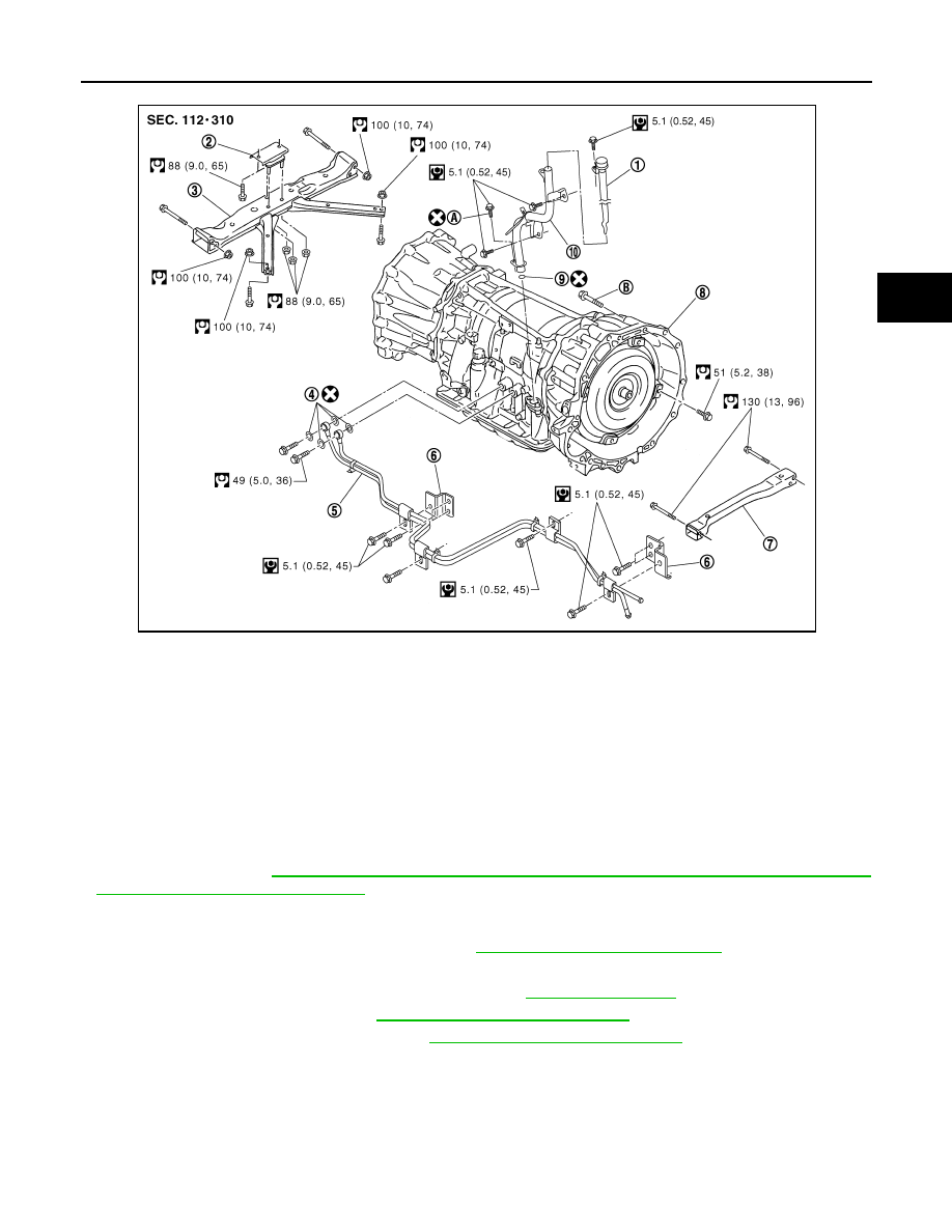
1.
A/T fluid level gauge
2.
Insulator
3.
A/T crossmember
4.
Copper sealing washers
5.
A/T fluid cooler tube
6.
Bracket
7.
Front crossmember
8.
Transmission assembly
9.
O-ring
10. A/T fluid charging pipe
A. Self-sealing bolt
B. Refer to installation.
WCIA0574E