Nissan Xterra. Manual - part 611


  Index      Nissan     Nissan Xterra (2014 year) - Service and Repair Manual


Search            


Content   ..  609  610  611  612   ..


Nissan Xterra. Manual - part 611


HYDRAULIC LINE

ST-19

< REMOVAL AND INSTALLATION >

C

D

E

F

H

I

J

K

L

M

A

B

ST

N

O

P

HYDRAULIC LINE

Removal and Installation

INFOID:0000000009483754

CAUTION:

Do not reuse O-rings or copper sealing washers.

NOTE:

When removing components such as hoses, tubes/lines, etc., cap or plug openings to prevent fluid from spill-

ing.

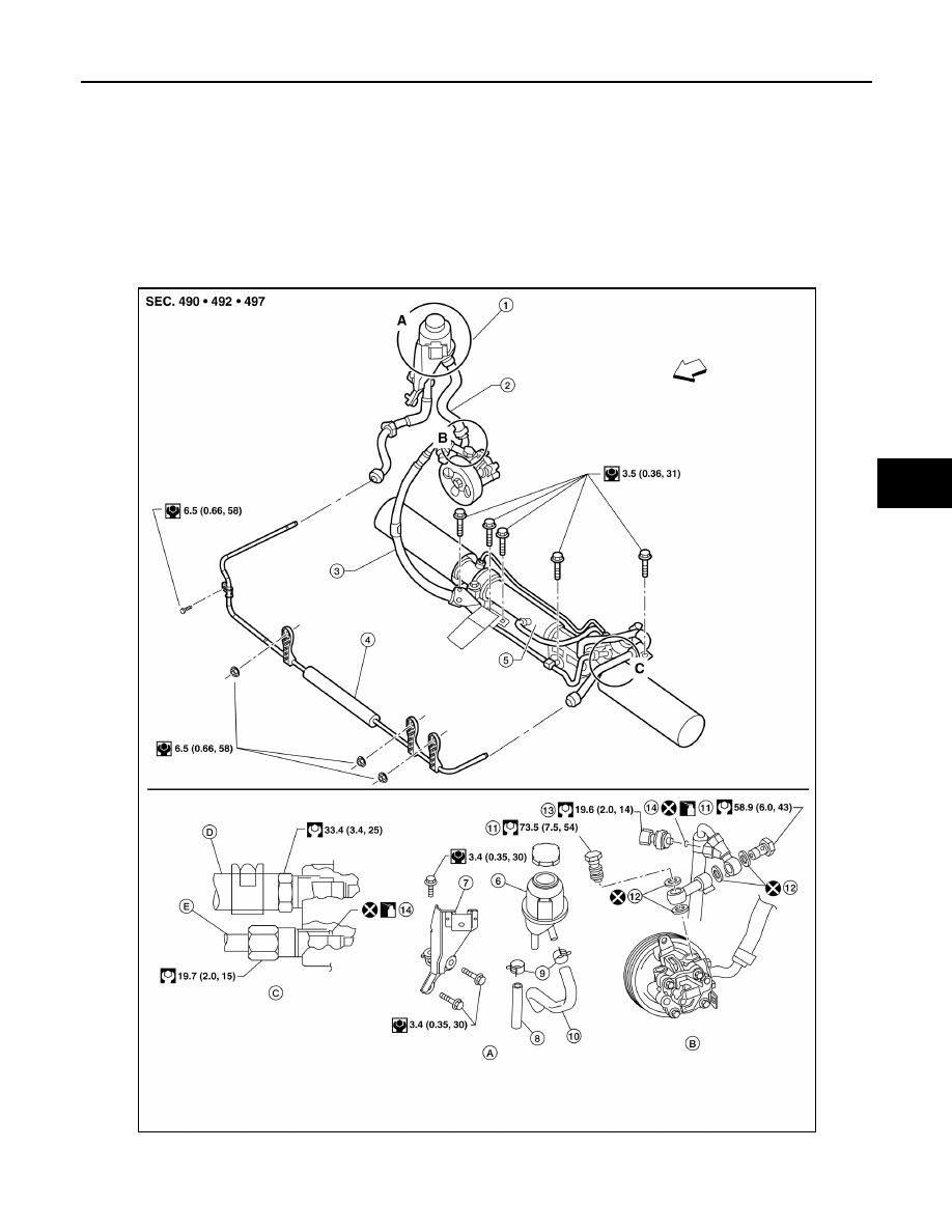
Refer to the following illustration for hydraulic line removal and installation.

AWGIA0195GB

1.

Reservoir tank

2.

Suction hose

3.

High pressure hose

4.

Oil cooler

5.

Steering gear assembly

6.

Reservoir tank

ST-20

< REMOVAL AND INSTALLATION >

HYDRAULIC LINE

7.

Reservoir tank bracket

8.

Return hose

9.

Hose clamps

10. Suction hose

11. Connector bolts

12. Copper sealing washers

13. Pressure sensor

14. O-ring

A.

Reservoir tank attachment

B.

Power steering pump connec-
tions

C.

Steering gear assembly con-
nections

D.

Low pressure hose

E.

High pressure hose

Genuine Nissan PSF or 
equivalent

Front

STEERING COLUMN

ST-21

< UNIT DISASSEMBLY AND ASSEMBLY >

C

D

E

F

H

I

J

K

L

M

A

B

ST

N

O

P

UNIT DISASSEMBLY AND ASSEMBLY

STEERING COLUMN

Disassembly and Assembly

INFOID:0000000009483755

DISASSEMBLY

1. Remove the bolt from the upper joint, then remove the upper joint from the steering column assembly.
2. Remove the ignition switch tamper resistant self-shear screws, using a drill.
3. Remove the ignition switch from the steering column.

ASSEMBLY

Assembly is in the reverse order of disassembly.

CAUTION:

• Do not reuse the self-shear screws.

• Any time the ignition switch has been removed and installed,

the keys must be re-registered in the BCM. Refer to CONSULT

Immobilizer mode and follow the on-screen instructions.

1.

Steering column assembly

2. Upper joint

3.

Ignition switch

4.

Self-shear screw

WGIA0126E

WGIA0009E

ST-22

< UNIT DISASSEMBLY AND ASSEMBLY >

STEERING COLUMN

INSPECTION AFTER ASSEMBLY

When the steering wheel does not turn smoothly, check as follows:
1. Check the steering column for the following:

• Damage to the column tube or bearings

• Wear around the seal edges

• Corrosion or pitting around the seal sliding area

Replace the steering column as an assembly, if necessary.

CAUTION:

• Do not exert any axial load or impact to the steering column.

• Replace the column if it is depleted of grease, worn, damaged, or if any scratches or coating

separation is present on the shaft seal area.

2. If the vehicle has been in a collision, or if noises are heard com-

ing from the steering column, check column length. If out of

specification, replace the steering column as an assembly.

3. Check the tilt device for proper operation range.

Steering column 
length (L)

: Refer to 

ST-28, "Steering Column"

AWGIA0147ZZ

Range (A)

: Refer to 

ST-28, "Steering Column"

WGIA0083E


Content   ..  609  610  611  612   ..