Nissan Xterra. Manual - part 456
HAC-22
< DTC/CIRCUIT DIAGNOSIS >
[MANUAL AIR CONDITIONER]
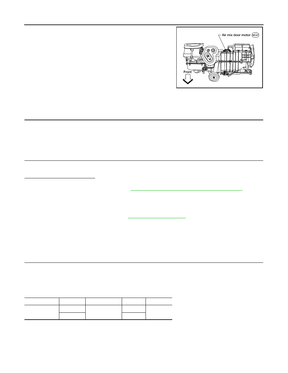
AIR MIX DOOR MOTOR
The air mix door motor is attached to the heater and cooling unit
assembly. This motor rotates so that the air mix door is opened or
closed to a position set by the front air control. Motor rotation is then
conveyed through a shaft and the air mix door position is then fed
back to the front air control by the PBR built into the air mix door
motor.
Air Mix Door Motor Component Function Check
INFOID:0000000009482472
INSPECTION FLOW
1.
CONFIRM SYMPTOM BY PERFORMING OPERATIONAL CHECK - TEMPERATURE INCREASE
1. Blower must be ON.
2. Turn the temperature control dial clockwise to maximum heat.
3. Check for hot air at discharge air outlets.
>> GO TO 2.
2.
CONFIRM SYMPTOM BY PERFORMING OPERATIONAL CHECK - TEMPERATURE DECREASE
1. Turn the temperature control dial counterclockwise to maximum cold.
2. Check for cold air at discharge air outlets.
Is the inspection results normal?
YES
>> Inspection End.
NO
>> Go to diagnosis procedure. Refer to
HAC-22, "Air Mix Door Motor Diagnosis Procedure"
.
Air Mix Door Motor Diagnosis Procedure
INFOID:0000000009482473
Regarding Wiring Diagram information, refer to
SYMPTOM:
• Discharge air temperature does not change.
• Air mix door motor does not operate.
DIAGNOSTIC PROCEDURE FOR AIR MIX DOOR MOTOR
1.
CHECK AIR MIX DOOR MOTOR CIRCUITS FOR OPEN AND SHORT TO GROUND
1. Turn ignition switch OFF.
2. Disconnect the front air control harness connector M50 and the air mix door motor harness connector
M147.
3. Check continuity between front air control harness connector M50 terminals 17, 18 and the air mix door
motor harness connector M147 terminals 5, 6.
WJIA1636E
Connector
Terminal
Connector
Terminal
Continuity
M50
18
M147
6
Yes
17
5