Nissan Xterra. Manual - part 371


  Index      Nissan     Nissan Xterra (2014 year) - Service and Repair Manual


Search            


Content   ..  369  370  371  372   ..


Nissan Xterra. Manual - part 371


EM-112

< UNIT DISASSEMBLY AND ASSEMBLY >

[VQ40DE]

ENGINE UNIT

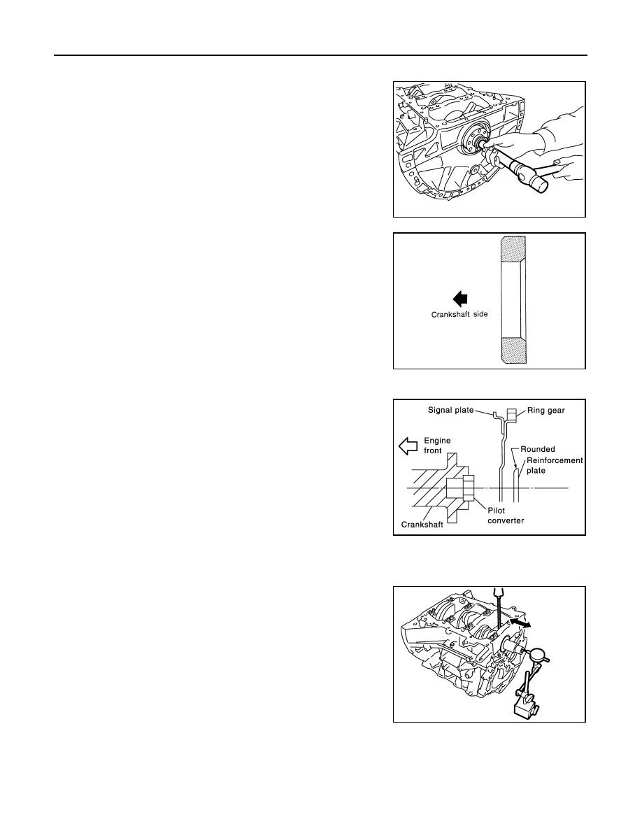
Pilot converter (A/T models)

• Install pilot converter.

• With drift of the following outer diameter, press-fit as far as it

will go.

• Press-fit pilot converter with its chamfer facing crankshaft as

shown. 

Drive plate (A/T models) 

• Install drive plate and reinforcement plate as shown.

• Hold ring gear using Ring Gear Stopper Tool.

• Tighten bolts crosswise over several times.

Inspection After Disassembly

INFOID:0000000009484493

CRANKSHAFT END PLAY

• Measure the clearance between thrust bearings and crankshaft

arm when crankshaft is moved fully forward or backward with dial

indicator.

• If the measured value exceeds the limit, replace thrust bearings,

and measure again. If it still exceeds the limit, replace crankshaft

also.

CONNECTING ROD SIDE CLEARANCE

Pilot converter

: Approximately 33 mm 
(1.30 in)

PBIC2947E

SEM537E

Tool number

: KV11105210 (J-44716)

PBIC0910E

Standard

: 0.10 - 0.25 mm (0.0039 - 0.0098 in)

Limit

: 0.30 mm (0.0118 in)

PBIC2953E

ENGINE UNIT

EM-113

< UNIT DISASSEMBLY AND ASSEMBLY >

[VQ40DE]

C

D

E

F

G

H

I

J

K

L

M

A

EM

N

P

O

• Measure the side clearance between connecting rod and crank-

shaft arm with feeler gauge.

• If the measured value exceeds the limit, replace connecting rod,

and measure again. If it still exceeds the limit, replace crankshaft

also.

PISTON TO PISTON PIN CLEARANCE

Piston Pin Hole Diameter

Measure the inner diameter of piston pin hole with inside microme-

ter.

Piston Pin Outer Diameter

Measure the outer diameter of piston pin with micrometer.

Piston to Piston Pin Oil Clearance

(Piston to piston pin oil clearance) = (Piston pin hole diameter) – (Piston pin outer diameter)

• If the calculated value is out of the standard, replace piston and piston pin assembly.

• When replacing piston and piston pin assembly. Refer to 

EM-125, "How to Select Piston and Bearing"

.

NOTE:

• Piston is available together with piston pin as assembly.

• Piston pin (piston pin hole) grade is provided only for the parts installed at the plant. For service parts, no

piston pin grades can be selected. (Only “0” grade is available.)

PISTON RING SIDE CLEARANCE

Standard

: 0.20 - 0.35 mm (0.0079 - 0.0138 in)

Limit

: 0.40 mm (0.0157 in)

PBIC2954E

Standard

: 21.993 - 22.005 mm (0.8659 - 0.8663 in)

PBIC0116E

Standard

: 21.989 - 22.001 mm (0.8657 - 0.8662 in)

PBIC0117E

Standard

: 0.002 - 0.006 mm (0.0001 - 0.0002 in)

EM-114

< UNIT DISASSEMBLY AND ASSEMBLY >

[VQ40DE]

ENGINE UNIT

• Measure side clearance of piston ring and piston ring groove with

feeler gauge.

• If the measured value exceeds the limit, replace piston ring, and measure again. If it still exceeds the limit,

replace piston also.

PISTON RING END GAP

• Make sure that the cylinder bore inner diameter is within the speci-

fication. Follow the "Cylinder Bore Inner Diameter" procedure.

• Lubricate with new engine oil to piston and piston ring, and then

insert piston ring until middle of cylinder with piston, and measure

the piston ring end gap with feeler gauge.

• If the measured value exceeds the limit, replace piston ring, and measure again.

CONNECTING ROD BEND AND TORSION

Standard:

Top ring

: 0.045 - 0.080 mm (0.0018 - 0.0031 in)

2nd ring

: 0.030 - 0.070 mm (0.0012 - 0.0028 in)

Oil ring

: 0.065 - 0.135 mm (0.0026 - 0.0053 in)

Limit:
  Top ring

: 0.11 mm (0.0043 in)

  2nd ring

: 0.10 mm (0.0039 in)

SEM024AA

Standard:

Top ring

: 0.23 - 0.33 mm (0.0091 - 0.0130 in)

2nd ring

: 0.33 - 0.48 mm (0.0130 - 0.0189 in)

Oil ring

: 0.20 - 0.50 mm (0.0079 - 0.0197 in)

Limit:
  Top ring

: 0.56 mm (0.0220 in)

  2nd ring

: 0.68 mm (0.0268 in)

Oil ring

: 0.85 mm (0.0335 in)

PBIC0118E

ENGINE UNIT

EM-115

< UNIT DISASSEMBLY AND ASSEMBLY >

[VQ40DE]

C

D

E

F

G

H

I

J

K

L

M

A

EM

N

P

O

• Check with connecting rod aligner.

• If it exceeds the limit, replace connecting rod assembly.

CONNECTING ROD DIAMETER (BIG END)

• Install connecting rod bearing cap without installing connecting rod

bearing, and tightening connecting rod bolts to the specified

torque. Refer to 

EM-103, "Disassembly and Assembly"

 for the

tightening procedure.

• Measure the inner diameter of connecting rod big end with inside

micrometer.

• If out of the standard, replace connecting rod assembly.

CONNECTING ROD BUSHING OIL CLEARANCE (SMALL END)

Connecting Rod Bushing Inside Diameter (Small End)

Measure inside diameter of connecting rod bushing using suitable

tool.

Piston Pin Diameter

Bend:

Limit: 0.15 mm (0.0059 in) per 100 mm (3.94 in) length

Torsion:

Limit: 0.30 mm (0.0118 in) per 100 mm (3.94 in) length

PBIC2077E

Standard

: 57.000 - 57.013 mm (2.2441 - 2.2446 in)

PBIC1641E

Standard

: 22.000 - 22.012 mm (0.8661 - 0.8666 in)

PBIC0120E


Content   ..  369  370  371  372   ..