Nissan Xterra. Manual - part 201
DLK-46
< DTC/CIRCUIT DIAGNOSIS >
KEYFOB BATTERY AND FUNCTION
KEYFOB BATTERY AND FUNCTION
Description
INFOID:0000000009485055
The following functions are available when having and carrying electronic ID.
• Door lock/unlock
• Panic alarm
Remote control entry function and panic alarm function are available when operating the remote buttons.
Component Function Check
INFOID:0000000009485056
NOTE:
The Signal Tech II Tool (J-50190) can be used to test the remote keyless entry keyfob relative signal strength.
Refer to the Signal Tech II User Guide for additional information.
1.
CHECK FUNCTION
With CONSULT
Check remote keyless entry receiver "MULTI REMOTE ENT" in Data Monitor mode with CONSULT. Refer to
BCS-18, "MULTI REMOTE ENT : CONSULT Function (BCM - MULTI REMOTE ENT)"
Is the inspection result normal?
YES
>> Key fob is OK.
NO
>> Refer to
.
Diagnosis Procedure
INFOID:0000000009485057
NOTE:
The Signal Tech II Tool (J-50190) can be used to test the remote keyless entry keyfob relative signal strength.
Refer to the Signal Tech II User Guide for additional information.
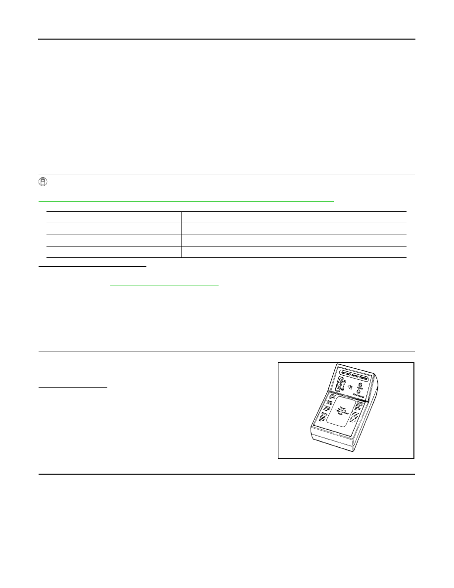
1.
CHECK KEYFOB FUNCTION
Check keyfob function using Signal Tech II Tool J-50190 or Remote
Keyless Entry Tester J-43241 (shown).
Does the test pass?
YES
>> Key fob is OK.
NO
>> GO TO 2
2.
CHECK KEY FOB COMPONENTS
Monitor item
Condition
KEYLESS LOCK
Indicates condition of lock signal from keyfob.
KEYLESS UNLOCK
Indicates condition of unlock signal from keyfob.
KEYLESS PANIC
Indicates condition of panic signal from keyfob.
LEL946A