Nissan Xterra. Manual - part 198
DLK-34
< DTC/CIRCUIT DIAGNOSIS >
KEY CYLINDER SWITCH
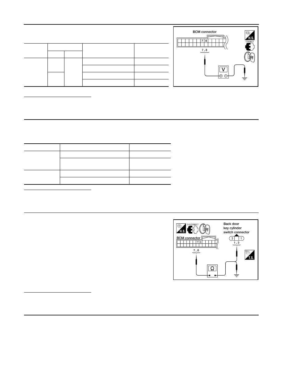
Check voltage between BCM connector M18 terminals 7, 8 and
ground.
Is the inspection result normal?
YES
>> Back door key cylinder switch signal is OK.
NO
>> GO TO 2
2.
CHECK BACK DOOR KEY CYLINDER SWITCH
1. Turn ignition switch OFF.
2. Disconnect back door key cylinder switch.
3. Check continuity between back door key cylinder switch terminals 1, 2 and 3.
Is the inspection result normal?
YES
>> GO TO 3
NO
>> Replace back door key cylinder switch.
3.
CHECK BACK DOOR KEY CYLINDER SWITCH HARNESS
1. Disconnect BCM.
2. Check continuity between BCM connector M18 terminals 7, 8
and back door key cylinder switch connector D505 terminals 3,
1.
3. Check continuity between BCM connector M18 terminals 7, 8
and ground.
Is the inspection result normal?
YES
>> GO TO 4
NO
>> Repair or replace harness.
4.
CHECK BACK DOOR KEY CYLINDER SWITCH GROUND
Connector
Terminals
Condition
Voltage (V)
(Approx.)
(+)
(–)
M18
7
Ground
Neutral/Lock
1.5
Unlock
0
8
Neutral/Unlock
1.5
Lock
0
WIIA0457E
Terminals
Condition
Continuity
1 – 2
Key is turned to LOCK.
Yes
Key is in N position or turned to UN-
LOCK
No
3 – 2
Key is turned to UNLOCK.
Yes
Key is in N position or turned to LOCK
No
7 - 3
: Continuity should exist.
8 - 1
: Continuity should exist.
7 - Ground
: Continuity should not exist.
8 - Ground
: Continuity should not exist.
WIIA0680E