Nissan Xterra. Manual - part 174


  Index      Nissan     Nissan Xterra (2014 year) - Service and Repair Manual


Search            


Content   ..  172  173  174  175   ..


Nissan Xterra. Manual - part 174


ENGINE COOLANT

CO-11

< PERIODIC MAINTENANCE >

[VQ40DE]

C

D

E

F

G

H

I

J

K

L

M

A

CO

N

P

O

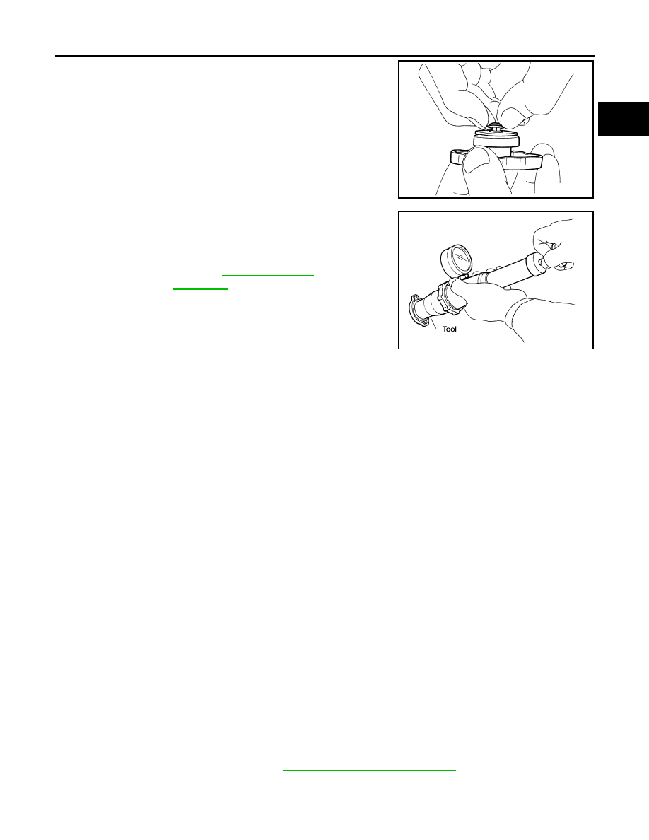
2. Pull the negative-pressure valve to open it and check that it

closes completely when released.

• Check that there is no dirt or damage on the valve seat of the

reservoir cap negative-pressure valve.

• Check that there are no abnormalities in the opening and clos-

ing conditions of the negative-pressure valve.

3. Check reservoir cap relief pressure using suitable tool and Tool.

NOTE:

• Apply engine coolant to the cap seal surface. 

• Replace the reservoir cap if there is any damage in the nega-

tive-pressure valve, or if the open-valve pressure is outside of

the limit.

CHECKING RADIATOR CAP

Inspect the radiator cap.

NOTE:

Thoroughly wipe out the radiator filler neck to remove any waxy residue or foreign material.

• Replace the cap if deposits of waxy residue or other foreign material are on the black rubber gasket or the

metal retainer.

CHECKING RADIATOR

Check radiator for mud or clogging. If necessary, clean radiator as follows.

CAUTION:

• Be careful not to bend or damage the radiator fins.

• When radiator is cleaned without removal, remove all surrounding parts such as cooling fan shroud

and horns. Then tape the harness connectors to prevent water from entering.

1. Spray water to the back side of the radiator core using a side to side motion from the top down. 
2. Stop spraying when debris no longer flows from radiator core. 
3. Blow air into the back side of radiator core using a side to side motion from the top down.

• Use compressed air lower than 490 kPa (5 kg/cm

2

, 71 psi) and keep distance more than 30 cm (11.8 in). 

4. Continue to blow air until no water sprays out.
5. Check for coolant leaks. Repair as necessary.

Changing Engine Coolant

INFOID:0000000009484582

WARNING:

Do not remove the radiator cap when the engine is hot. Serious burns could occur from high-pressure

engine coolant escaping from the radiator. Wrap a thick cloth around the radiator cap. Slowly turn it a

quarter of a turn to release built-up pressure. Carefully remove radiator cap by turning it all the way.

DRAINING ENGINE COOLANT

1. Turn ignition switch ON and set temperature control lever all the way to HOT position or the highest tem-

perature position. Wait 10 seconds and turn ignition switch OFF.

2. Remove the engine under cover. Refer to 

EXT-15, "Removal and Installation"

.

SMA967B

Tool number

: EG17650301 (J-33984-A)

Standard

: Refer to 

CO-30, "Standard 

and Limit"

.

WBIA0570E

CO-12

< PERIODIC MAINTENANCE >

[VQ40DE]

ENGINE COOLANT

3. Open the radiator drain plug at the bottom of the radiator, and

remove the reservoir cap. This is the only step required when

partially draining the cooling system (radiator only). 

CAUTION:

• Do not to allow the coolant to contact the drive belts.

• Perform this step when engine is cold.

4. When draining all of the coolant in the system for engine

removal or repair, it is necessary to drain the cylinder block.

Remove the cylinder block drain plugs (A), (B), (C), (D) and

block heater (if equipped), to drain the cylinder block as shown.

CAUTION:

Do not reuse copper sealing washers.

NOTE:

For Canada, the (D) cylinder block drain plug as shown, is not a

cylinder block drain plug but a block heater.

5. Remove the reservoir tank to drain the engine coolant, then clean the reservoir tank before installing it.
6. Check the drained coolant for contaminants such as rust, corrosion or discoloration.

If the coolant is contaminated, flush the engine cooling system. Follow the "Flushing Cooling System" pro-

cedure.

REFILLING ENGINE COOLANT

LLIA0070E

WLIA0020E

ENGINE COOLANT

CO-13

< PERIODIC MAINTENANCE >

[VQ40DE]

C

D

E

F

G

H

I

J

K

L

M

A

CO

N

P

O

1. Close the radiator drain plug. Install the reservoir tank, cylinder

block drain plugs (A), (B), (C), (D) and block heater (if

equipped). 

• The radiator must be completely empty of coolant and water.

• Apply sealant to the threads of the cylinder block drain plugs

(A), (B), (C), (D). Use Genuine High Performance Thread

Sealant or equivalent. Refer to 

GI-21, "Recommended Chemi-

cal Products and Sealants"

.

• Tighten each plug to the specified torque. Refer to 

EM-103,

"Disassembly and Assembly"

.

CAUTION:

Do not reuse copper sealing washers.

2. Set the vehicle heater controls to the full HOT and heater ON position. Turn the vehicle ignition ON with

the engine OFF as necessary to activate the heater mode.

3. Remove the vented reservoir cap and replace it with a non-vented reservoir cap before filling the cooling

system.

4. Install the Tool by installing the radiator cap adapter onto the

radiator neck opening. Then attach the gauge body assembly

with the refill tube and the venturi assembly to the radiator cap

adapter.

5. Insert the refill hose into the coolant mixture container that is

placed at floor level. Make sure the ball valve is in the closed

position. 

CAUTION:

Do not use any cooling system additives such as radiator

sealer. Additives may clog the cooling system and cause

damage to the engine, transmission and/or cooling system.

NOTE:

Use recommended coolant or equivalent. Refer to 

MA-12, "Flu-

ids and Lubricants"

.

6. Install an air hose to the venturi assembly, the air pressure must

be within specification. 

CAUTION:

The compressed air supply must be equipped with an air dryer.

7. The vacuum gauge will begin to rise and there will be an audible hissing noise. During this process open

the ball valve on the refill hose slightly. Rising coolant will be visible in the refill hose. After the refill hose is

full of coolant, close the ball valve. This will purge air trapped in the refill hose.

WLIA0020E

Tool number

: KV991J0070 (J-45695)

Cooling system capacity 
(with reservoir)

: Refer to 

MA-12, "Fluids 

and Lubricants"

.

Compressed air 
supply pressure

: 549 - 824 kPa (5.6 - 8.4 kg/cm

2

80 - 119 psi)

LLIA0058E

CO-14

< PERIODIC MAINTENANCE >

[VQ40DE]

ENGINE COOLANT

8. Continue to draw the vacuum until the gauge reaches 28 inches

of vacuum. The gauge may not reach 28 inches in high altitude

locations. Refer to the following vacuum specifications. 

9. When the vacuum gauge has reached the specified amount, disconnect the air hose and wait 20 seconds

to see if the system loses vacuum. If the vacuum level drops, perform necessary repairs to the system

and repeat steps 6 - 8 to bring the vacuum to the specified amount. Recheck for leaks. 

10. Place the coolant container (with the refill hose inserted) at the same level as the top of the radiator. Then

open the ball valve on the refill hose so the coolant will be drawn up to fill the cooling system. The cooling

system is full when the vacuum gauge reads zero.

CAUTION:

Do not allow the coolant container to get too low when filling, to avoid air from being drawn into

the cooling system. 

11. Remove the Tool from the radiator neck opening and install the radiator cap.
12. Remove the non-vented reservoir cap.
13. Fill the cooling system reservoir tank to the specified level. Run the engine to warm up the cooling system

and top up the system as necessary before installing the vented reservoir cap.

14. Install the engine under cover. Refer to 

EXT-15, "Removal and Installation"

.

FLUSHING COOLING SYSTEM

1. Drain the water from the engine cooling system. Refer to 

CO-11, "Changing Engine Coolant"

.

2. Fill the radiator and the reservoir tank (to the “MAX” line), with water. Reinstall the radiator cap and leave

the vented reservoir cap off.

3. Run the engine until it reaches normal operating temperature.
4. Press the engine accelerator two or three times under no-load.
5. Stop the engine and wait until it cools down.
6. Drain the water from the engine cooling system. Refer to 

CO-11, "Changing Engine Coolant"

.

7. Repeat steps 2 through 6 until clear water begins to drain from the radiator.

Altitude above sea level

Vacuum gauge reading

0 - 100 m (328 ft)

: 28 inches of vacuum

300 m (984 ft)

: 27 inches of vacuum

500 m (1,641 ft)

: 26 inches of vacuum

1,000 m (3,281 ft)

: 24 - 25 inches of vacuum

LLIA0057E


Content   ..  172  173  174  175   ..