Nissan Xterra. Manual - part 171


  Index      Nissan     Nissan Xterra (2014 year) - Service and Repair Manual


Search            


Content   ..  169  170  171  172   ..


Nissan Xterra. Manual - part 171


CL-18

< SERVICE DATA AND SPECIFICATIONS (SDS) 

SERVICE DATA AND SPECIFICATIONS (SDS)

SERVICE DATA AND SPECIFICATIONS (SDS)

SERVICE DATA AND SPECIFICATIONS (SDS)

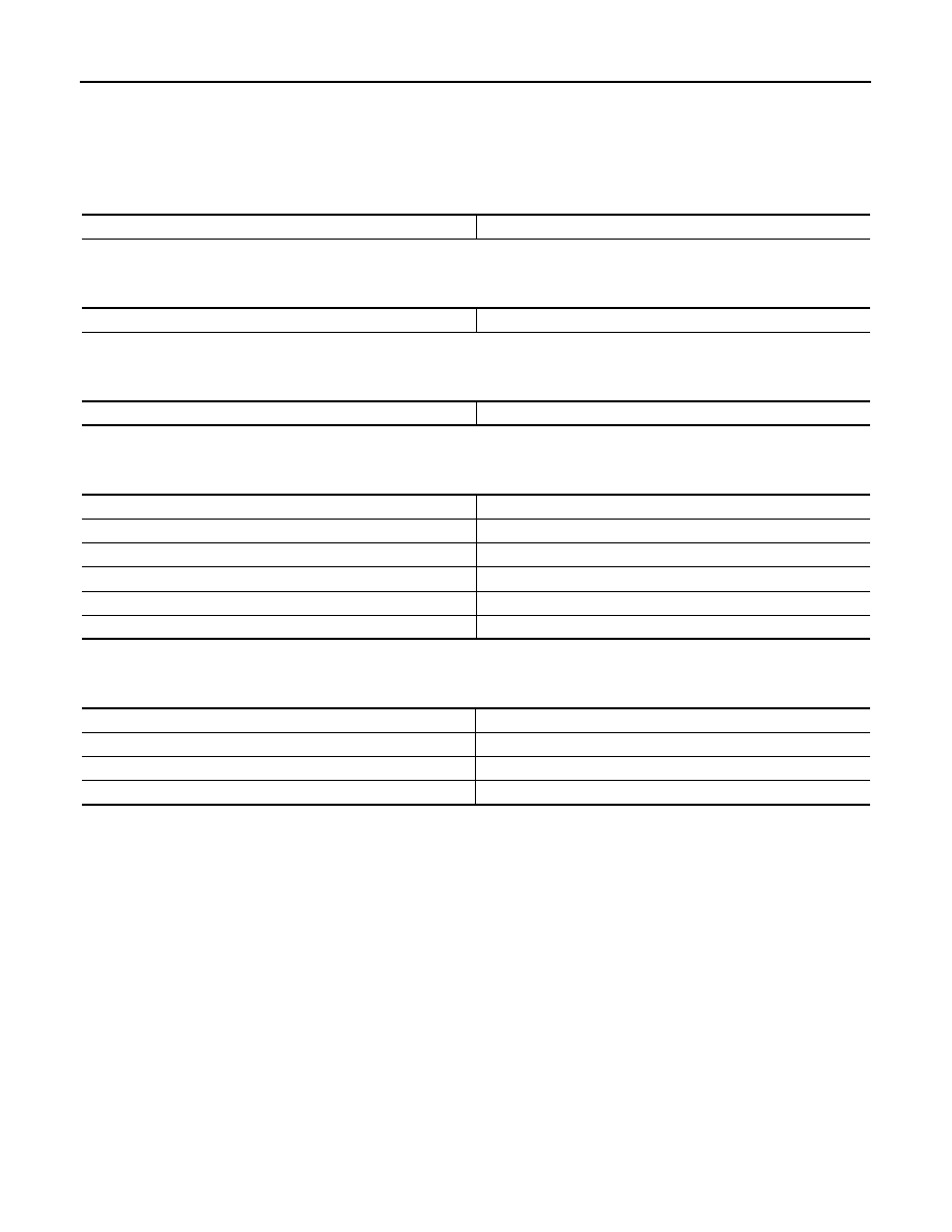
Clutch Control System

INFOID:0000000009483552

Clutch Master Cylinder

INFOID:0000000009483553

Unit: mm (in)

Clutch Operating Cylinder

INFOID:0000000009483554

Unit: mm (in)

Clutch Disc

INFOID:0000000009483555

Unit: mm (in)

Clutch Cover

INFOID:0000000009483556

Unit: mm (in)

Type of clutch control

Hydraulic

Inner diameter

15.87 (5/8)

Inner diameter

19.05 (3/4)

Engine model

VQ40DE

Model

260

Facing size (Outer dia. 

× inner dia. × thickness)

260 

× 190 × 3.2 (10.24 × 7.48 × 0.126)

Wear limit (depth to rivet head)

0.3 (0.012)

Runout limit/diameter of the area to be measured

1.0 (0.039) or less/250 (9.84) dia.

Maximum backlash of spline (at outer disc edge)

1.0 (0.039)

Engine model

VQ40DE

Set-load

8340 N (850 kg, 1875 lb)

Diaphragm spring lever height

44.0 - 46.0 (1.732 - 1.811)

Uneven limit of diaphragm spring toe height

0.7 (0.028)

SERVICE DATA AND SPECIFICATIONS (SDS)

CL-19

< SERVICE DATA AND SPECIFICATIONS (SDS) 

C

E

F

G

H

I

J

K

L

M

A

B

CL

N

O

P

Clutch Pedal

INFOID:0000000009483557

Unit: mm (in)

Clearance (C) between pedal stopper rubber and clutch interlock switch threaded end 
while clutch pedal is fully depressed.

0.1 - 1.0 (0.004 - 0.039)

SCL800

CO-1

ENGINE

C

D

E

F

G

H

I

J

K

L

M

SECTION 

CO

A

CO

N

O

P

CONTENTS

ENGINE COOLING SYSTEM

VQ40DE

PRECAUTION ...............................................

2

PRECAUTIONS ...................................................

2

Precaution for Supplemental Restraint System 
(SRS) "AIR BAG" and "SEAT BELT PRE-TEN-
SIONER" .................................................................
..

2

Precaution for Liquid Gasket .....................................

2

PREPARATION ............................................

4

PREPARATION ...................................................

4

Special Service Tool  .................................................

4

Commercial Service Tool  ..........................................

4

SYSTEM DESCRIPTION  ..............................

6

COOLING SYSTEM ............................................

6

Cooling Circuit ...........................................................

6

Schematic .................................................................

7

OVERHEATING CAUSE ANALYSIS ..................

8

Troubleshooting Chart ...............................................

8

PERIODIC MAINTENANCE .........................

10

ENGINE COOLANT  ...........................................

10

System Inspection ...................................................

10

Changing Engine Coolant  .......................................

11

REMOVAL AND INSTALLATION ...............

15

RADIATOR ........................................................

15

Exploded View .........................................................

15

Removal and Installation  .........................................

15

ENGINE COOLING FAN ...................................

18

Exploded View .........................................................

18

Removal and Installation (Crankshaft driven type) ....

18

Removal and Installation (Motor driven type)  ..........

19

WATER PUMP  ..................................................

21

Exploded View .........................................................

21

Removal and Installation  .........................................

21

WATER INLET AND THERMOSTAT ASSEM-
BLY ....................................................................

26

Exploded View .........................................................

26

Removal and Installation  .........................................

26

WATER OUTLET AND WATER PIPING  ..........

28

Exploded View .........................................................

28

Removal and Installation  .........................................

28

SERVICE DATA AND SPECIFICATIONS 
(SDS) ............................................................

30

SERVICE DATA AND SPECIFICATIONS 
(SDS) .................................................................

30

Standard and Limit  ..................................................

30

CO-2

< PRECAUTION >

[VQ40DE]

PRECAUTIONS

PRECAUTION

PRECAUTIONS

Precaution for Supplemental Restraint System (SRS) "AIR BAG" and "SEAT BELT 
PRE-TENSIONER"

INFOID:0000000010201157

The Supplemental Restraint System such as “AIR BAG” and “SEAT BELT PRE-TENSIONER”, used along

with a front seat belt, helps to reduce the risk or severity of injury to the driver and front passenger for certain

types of collision. This system includes seat belt switch inputs and dual stage front air bag modules. The SRS

system uses the seat belt switches to determine the front air bag deployment, and may only deploy one front

air bag, depending on the severity of a collision and whether the front occupants are belted or unbelted.

Information necessary to service the system safely is included in the SR and SB section of this Service Man-

ual.

WARNING:

• To avoid rendering the SRS inoperative, which could increase the risk of personal injury or death in

the event of a collision which would result in air bag inflation, all maintenance must be performed by

an authorized NISSAN/INFINITI dealer.

• Improper maintenance, including incorrect removal and installation of the SRS, can lead to personal

injury caused by unintentional activation of the system. For removal of Spiral Cable and Air Bag

Module, see the SR section.

• Do not use electrical test equipment on any circuit related to the SRS unless instructed to in this

Service Manual. SRS wiring harnesses can be identified by yellow and/or orange harnesses or har-

ness connectors.

PRECAUTIONS WHEN USING POWER TOOLS (AIR OR ELECTRIC) AND HAMMERS

WARNING:

• When working near the Airbag Diagnosis Sensor Unit or other Airbag System sensors with the Igni-

tion ON or engine running, DO NOT use air or electric power tools or strike near the sensor(s) with a

hammer. Heavy vibration could activate the sensor(s) and deploy the air bag(s), possibly causing

serious injury.

• When using air or electric power tools or hammers, always switch the Ignition OFF, disconnect the

battery and wait at least three minutes before performing any service.

Precaution for Liquid Gasket

INFOID:0000000009484575

REMOVAL OF LIQUID GASKET 

• After removing the bolts and nuts, separate the mating surface and

remove the old liquid gasket using Tool.

CAUTION:

Do not damage the mating surfaces.

• Tap the seal cutter to insert it (1).

• In areas where the Tool is difficult to use, lightly tap to slide it (2).

LIQUID GASKET APPLICATION PROCEDURE

Tool number

: KV10111100 (J-37228)

WBIA0566E


Content   ..  169  170  171  172   ..