Nissan Xterra. Manual - part 131
C1143, C1144 STEERING ANGLE SENSOR
BRC-181
< DTC/CIRCUIT DIAGNOSIS >
[TYPE 2]
C
D
E
G
H
I
J
K
L
M
A
B
BRC
N
O
P
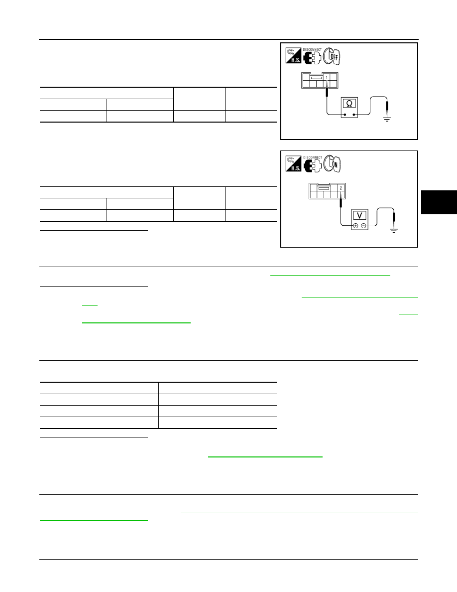
1. Turn ignition switch OFF.
2. Disconnect steering angle sensor connector.
3. Check continuity between steering angle sensor connector M47
terminal 1 and ground.
4. Turn ignition switch ON.
5. Check voltage between steering angle sensor connector M47
terminal 2 and ground.
Is the inspection result normal?
YES
>> GO TO 3
NO
>> Repair or replace malfunctioning components.
3.
CHECK DATA MONITOR
Perform the steering angle sensor component inspection. Refer to
BRC-181, "Component Inspection"
.
Is the inspection result normal?
YES
>> Replace ABS actuator and electric unit (control unit). Refer to
BRC-234, "Removal and Installa-
.
NO
>> Replace steering angle sensor and adjust neutral position of steering angle sensor. Refer to
236, "Removal and Installation"
Component Inspection
INFOID:0000000009482804
1.
CHECK DATA MONITOR
Select “STR ANGLE SIG” in “DATA MONITOR” and check steering angle sensor signal.
Is the inspection result normal?
YES
>> Inspection End
NO
>> Go to diagnosis procedure. Refer to
BRC-180, "Diagnosis Procedure"
.
Special Repair Requirement
INFOID:0000000009482805
1.
ADJUSTMENT OF STEERING ANGLE SENSOR NEUTRAL POSITION
Always perform neutral position adjustment for the steering angle sensor when replacing the ABS actuator
and electric unit (control unit). Refer to
BRC-122, "ADJUSTMENT OF STEERING ANGLE SENSOR NEU-
>> GO TO 2
2.
CALIBRATION OF DECEL G SENSOR
Steering angle sensor
—
Continuity
Connector
Terminal
M47
1
Ground
Yes
AWFIA0447ZZ
Steering angle sensor
—
Voltage
Connector
Terminal
M47
2
Ground
Battery voltage
AWFIA0448ZZ
Steering condition
STR ANGLE SIG (DATA MONITOR)
Driving straight
0
±2.5 °
Turn 90
° to left
Approx. +90
°
Turn 90
° to right
Approx.
−90 °