Nissan Xterra. Manual - part 126
C1110, C1170 ABS ACTUATOR AND ELECTRIC UNIT (CONTROL UNIT)
BRC-161
< DTC/CIRCUIT DIAGNOSIS >
[TYPE 2]
C
D
E
G
H
I
J
K
L
M
A
B
BRC
N
O
P
C1110, C1170 ABS ACTUATOR AND ELECTRIC UNIT (CONTROL UNIT)
DTC Logic
INFOID:0000000009482761
DTC DETECTION LOGIC
DTC CONFIRMATION PROCEDURE
1.
CHECK SELF-DIAGNOSIS RESULTS
Check the self-diagnosis results.
Is above displayed on the self-diagnosis display?
YES
>> Proceed to diagnosis procedure. Refer to
BRC-161, "Diagnosis Procedure"
NO
>> Inspection End
Diagnosis Procedure
INFOID:0000000009482762
1.
REPLACE ABS ACTUATOR AND ELECTRIC UNIT (CONTROL UNIT)
>> Replace ABS actuator and electric unit (control unit). Refer to
BRC-234, "Removal and Installa-
.
Special Repair Requirement
INFOID:0000000009482763
1.
ADJUSTMENT OF STEERING ANGLE SENSOR NEUTRAL POSITION
Always perform neutral position adjustment for the steering angle sensor when replacing the ABS actuator
and electric unit (control unit). Refer to
BRC-122, "ADJUSTMENT OF STEERING ANGLE SENSOR NEU-
>> GO TO 2
2.
CALIBRATION OF DECEL G SENSOR
Always perform calibration of decel G sensor when replacing the ABS actuator and electric unit (control unit).
BRC-123, "CALIBRATION OF DECEL G SENSOR : Description"
.
>> END
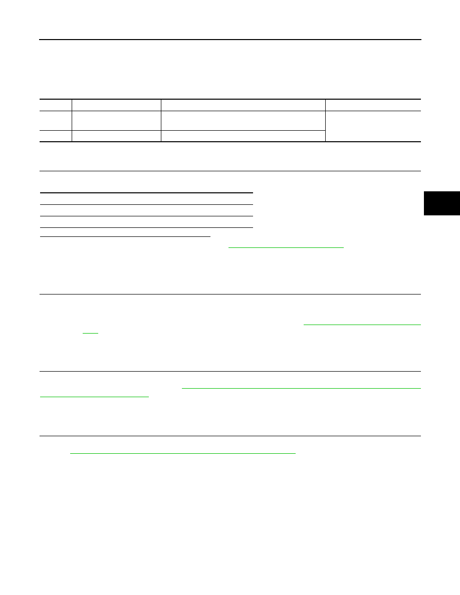
DTC
Display item
Malfunction detected condition
Possible cause
C1110
CONTROLLER FAILURE
When there is an internal malfunction in the ABS actuator
and electric unit (control unit).
• ABS actuator and electric unit
(control unit)
C1170
VARIANT CODING
In a case where VARIANT CODING is different.
Self-diagnosis results
CONTROLLER FAILURE
VARIANT CODING