Nissan Xterra. Manual - part 114


  Index      Nissan     Nissan Xterra (2014 year) - Service and Repair Manual


Search            


Content   ..  112  113  114  115   ..


Nissan Xterra. Manual - part 114


ACTUATOR AND ELECTRIC UNIT (ASSEMBLY)

BRC-113

< UNIT REMOVAL AND INSTALLATION >

[TYPE 1]

C

D

E

G

H

I

J

K

L

M

A

B

BRC

N

O

P

ACTUATOR AND ELECTRIC UNIT (ASSEMBLY)

Removal and Installation

INFOID:0000000009482707

NOTE:

When removing components such as hoses, tubes/lines, etc., cap or plug openings to prevent fluid from spill-

ing.

REMOVAL

1. Disconnect the negative battery terminal. Refer to 

PG-72, "Removal and Installation"

.

2. Remove air cleaner case. Refer to 

EM-24, "Exploded View"

.

3. Disconnect the harness connector from the ABS actuator and electric unit (control unit).
4. Disconnect the brake tubes.

CAUTION:

• To remove the brake tubes, use a flare nut wrench to prevent the flare nuts and brake tubes from

being damaged.

• Be careful not to splash brake fluid on painted areas; it may cause paint damage. If brake fluid is

splashed on painted areas, wash it away with water immediately.

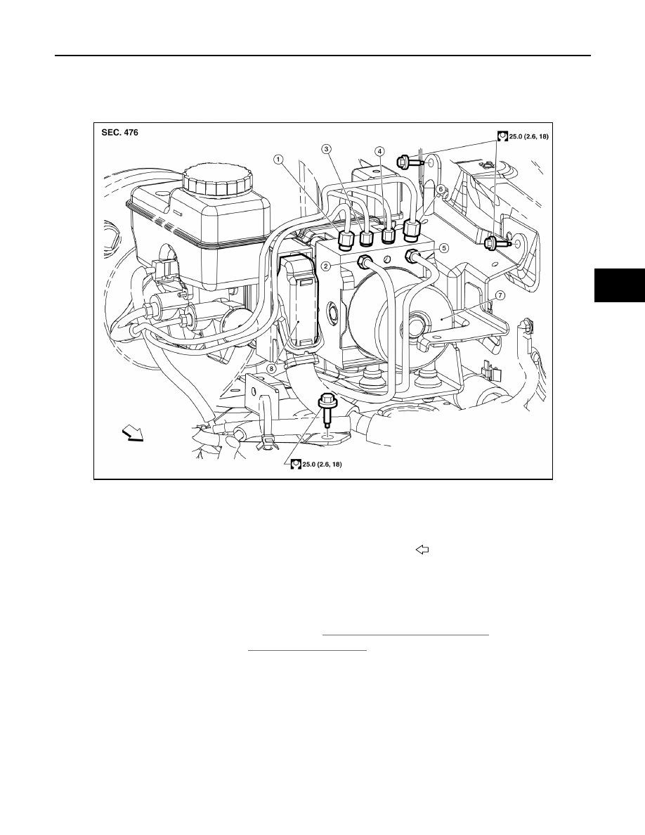
5. Remove three bolts, then remove the ABS actuator and electric unit (control unit) and bracket.
6. Remove the bolt and remove the bracket from the ABS actuator and electric unit (control unit).

INSTALLATION

1.

From master cylinder secondary side
18.2 N·m (1.9 kg-m, 13 ft-lb)

2.

To rear right disc brake
13.0 N·m (1.3 kg-m, 10 ft-lb)

3.

To rear left disc brake
13.0 N·m (1.3 kg-m, 10 ft-lb)

4.

To front right disc brake
13.0 N·m (1.3 kg-m, 10 ft-lb)

5.

To front left disc brake
13.0 N·m (1.3 kg-m, 10 ft-lb)

6.

From master cylinder primary side
18.2 N·m (1.9 kg-m, 13 ft-lb)

7.

ABS actuator and electric unit (control unit) 8.

Harness connector

Front

AWFIA0743GB

BRC-114

< UNIT REMOVAL AND INSTALLATION >

[TYPE 1]

ACTUATOR AND ELECTRIC UNIT (ASSEMBLY)

Installation is in the reverse order of removal.

• If the ABS actuator and electric unit (control unit) is replaced, make sure to adjust position of steering angle

sensor. Refer to 

BRC-12, "ADJUSTMENT OF STEERING ANGLE SENSOR NEUTRAL POSITION : Special

Repair Requirement"

.

CAUTION:

• All hoses and piping (tubes) must be free from excessive bending, twisting and pulling.

• Make sure there is no interference with other parts when turning steering both clockwise and coun-

terclockwise.

• The brake piping is an important safety part. If a brake fluid leak is detected, always disassemble the

parts. Replace applicable part with a new one, if necessary.

• Be careful not to splash brake fluid on painted areas; it may cause paint damage. If brake fluid is

splashed on painted areas, wash it away with water immediately.

• Do not bend or twist brake hose sharply, or strongly pull it.

• When removing components, cover connections so that no dirt, dust, or other foreign matter gets in.

• Do not reuse drained brake fluid.

• After installation of the ABS actuator and electric unit (control unit), refill brake system with new

brake fluid. Then bleed the air from the brake system. Refer to 

BR-17, "Bleeding Brake System"

.

ABS actuator and electric 
unit (control unit)

: 7.0 N·m (0.7 kg-m, 62 in-lb)

STEERING ANGLE SENSOR

BRC-115

< UNIT REMOVAL AND INSTALLATION >

[TYPE 1]

C

D

E

G

H

I

J

K

L

M

A

B

BRC

N

O

P

STEERING ANGLE SENSOR

Removal and Installation

INFOID:0000000009482708

REMOVAL

1. Remove the spiral cable. Refer to 

SR-13, "Removal and Installation"

.

2. Remove the screws and remove the steering angle sensor from the spiral cable.

INSTALLATION

Installation is in the reverse order of removal.

• Reset the neutral position of the steering angle sensor. Refer to 

BRC-12, "ADJUSTMENT OF STEERING

ANGLE SENSOR NEUTRAL POSITION : Special Repair Requirement"

.

CAUTION:

Any time the steering angle sensor is removed and installed or replaced, you must reset the neutral

position of the steering angle sensor. Refer to 

BRC-12, "ADJUSTMENT OF STEERING ANGLE SEN-

SOR NEUTRAL POSITION : Special Repair Requirement"

.

BRC-116

< UNIT REMOVAL AND INSTALLATION >

[TYPE 1]

YAW RATE/SIDE/DECEL G SENSOR

YAW RATE/SIDE/DECEL G SENSOR

Removal and Installation

INFOID:0000000009482709

REMOVAL

1. Remove center console rear base. Refer to 

IP-10, "Exploded View"

.

2. Remove yaw rate/side/decel G sensor attaching nuts as shown.

• The location of the yaw rate/side/decel G sensor is the same

for all models.

CAUTION:

• Do not use power tools to remove or install yaw rate/side/

decel G sensor.

• Do not drop or strike the yaw rate/side/decel G sensor.

3. Disconnect harness connector and remove the yaw rate/side/

decel G sensor.

INSTALLATION

Installation is in the reverse order of removal.

NOTE:

After performing the above work, calibrate the decel G sensor settings of the yaw rate/side/decel G sensor.

Refer to 

BRC-13, "CALIBRATION OF DECEL G SENSOR : Special Repair Requirement"

.

WFIA0230E


Content   ..  112  113  114  115   ..