Nissan Xterra. Manual - part 77


  Index      Nissan     Nissan Xterra (2014 year) - Service and Repair Manual


Search            


Content   ..  75  76  77  78   ..


Nissan Xterra. Manual - part 77


BRAKE FLUID

BR-17

< PERIODIC MAINTENANCE >

C

D

E

G

H

I

J

K

L

M

A

B

BR

N

O

P

BRAKE FLUID

On Board Inspection

INFOID:0000000009484647

LEVEL CHECK

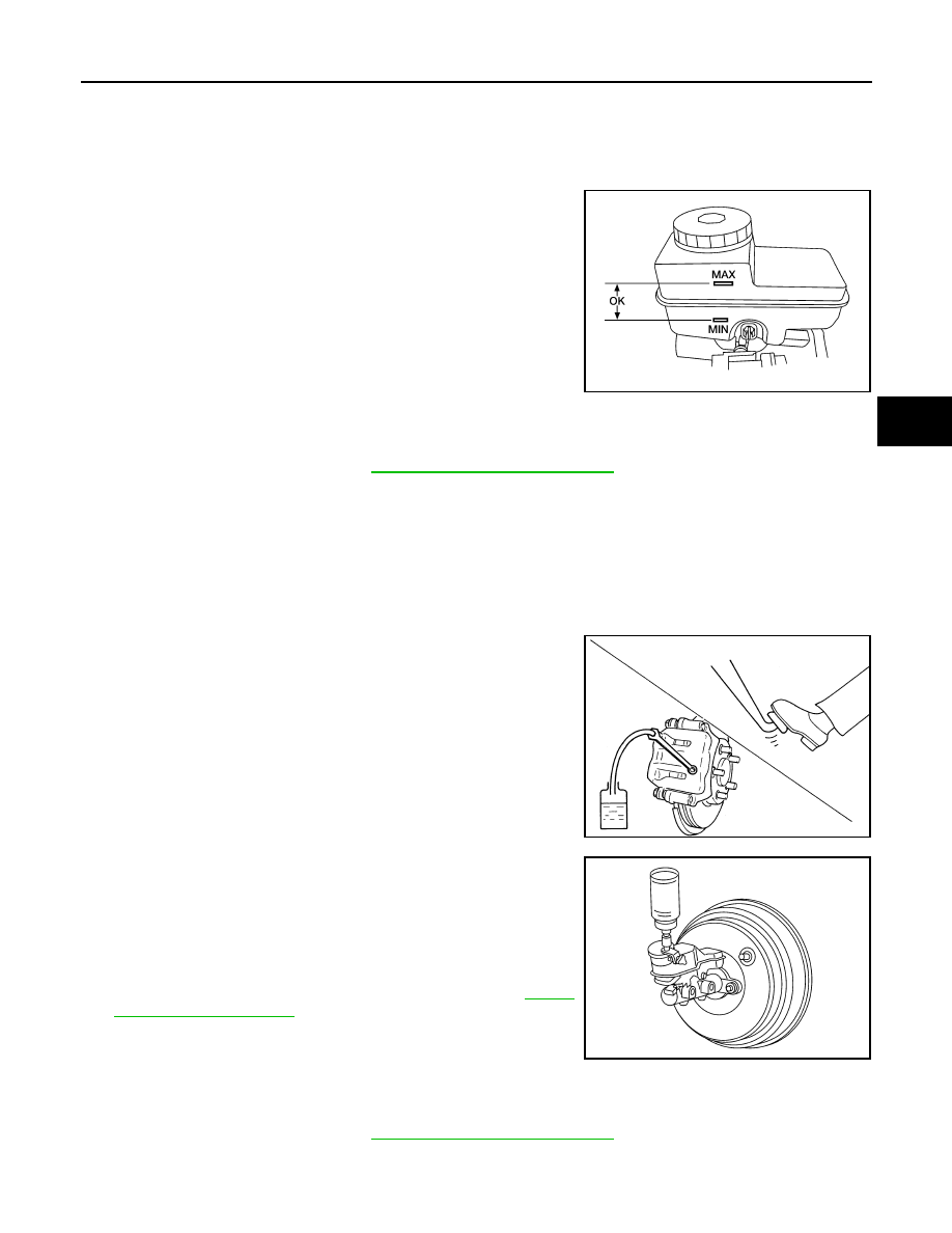
• Check that the brake fluid level in the reservoir tank is within speci-

fication, between the MAX and MIN lines as shown.

• Visually check around reservoir tank for fluid leaks.

• If fluid level is excessively low, check brake system for leaks.

• If brake warning lamp remains illuminated after the parking brake

pedal is released, check the brake system for any brake fluid

leaks.

Drain and Refill

INFOID:0000000009484648

CAUTION:

• Refill with new brake fluid. Refer to 

MA-12, "Fluids and Lubricants"

.

• Do not reuse drained brake fluid.

• Be careful not to splash brake fluid on painted areas; it may cause paint damage. If brake fluid is

splashed on painted areas, wash it away with water immediately.

• Before servicing, disconnect ABS actuator and electric unit (control unit) connector or battery nega-

tive terminal.

1. Turn ignition switch OFF and disconnect ABS actuator and electric unit (control unit) connector or battery

negative terminal.

2. Connect a vinyl tube to each bleed valve.
3. Depress brake pedal, loosen each bleed valve, and gradually

remove brake fluid.

4. Make sure there is no foreign material in reservoir tank, and refill

with new brake fluid.

5. Rest foot on brake pedal. Loosen bleed valve. Slowly depress

brake pedal until it stops. Tighten bleed valve. Release brake

pedal. Repeat the process a few times, then pause to add new

brake fluid to master cylinder. Continue until the new brake fluid

flows out of the bleed valve.

Bleed the air out of the brake hydraulic system. Refer to 

BR-17,

"Bleeding Brake System"

.

Bleeding Brake System

INFOID:0000000009484649

CAUTION:

• Refill with new brake fluid. Refer to 

MA-12, "Fluids and Lubricants"

.

• Do not reuse drained brake fluid.

LFIA0234E

BRA0007D

PFIA0403J

BR-18

< PERIODIC MAINTENANCE >

BRAKE FLUID

• Be careful not to splash brake fluid on painted areas; it may cause paint damage. If brake fluid is

splashed on painted areas, wash it away with water immediately.

• Before servicing, disconnect ABS actuator and electric unit (control unit) connector or battery nega-

tive terminal.

• While bleeding, monitor the master cylinder brake fluid level.
1. Turn ignition switch OFF and disconnect ABS actuator and electric unit (control unit) connector or battery

negative terminal.

2. Connect a vinyl tube to the rear right bleed valve.
3. Fully depress brake pedal 4 to 5 times.
4. With brake pedal depressed, loosen bleed valve to let the air out, and then tighten it immediately.
5. Repeat steps 3 and 4 until no more air comes out.
6. Tighten bleed valve to the specified torque. Refer to 

BR-34, "Exploded View of Brake Caliper"

 (front disc

brake), 

BR-39, "Exploded View of Brake Caliper"

 (rear disc brake). 

7. Perform steps 2 to 6 at each wheel, with master cylinder reservoir tank filled at least half way, bleed air

from the front left, rear left, and front right bleed valves, in that order.

BRAKE PEDAL

BR-19

< REMOVAL AND INSTALLATION >

C

D

E

G

H

I

J

K

L

M

A

B

BR

N

O

P

REMOVAL AND INSTALLATION

BRAKE PEDAL

Exploded View

INFOID:0000000009484650

NOTE:

The clevis pin may be installed from either direction.

Removal and Installation

INFOID:0000000009484651

REMOVAL

WARNING:

Do not deform the brake tube. 

CAUTION:

• Do not disassemble the brake pedal assembly.

• Avoid damage from dropping the brake pedal assembly during handling.

• Keep the brake pedal assembly away from water.
1. Remove the instrument lower panel LH. Refer to 

IP-14, "Removal and Installation"

.

2. Remove the stop lamp switch and ASCD cancel switch from the pedal assembly.
3. Remove snap pin and clevis pin from the clevis of the brake booster.
4. Remove the brake pedal assembly bolt.
5. Remove the pedal assembly nuts and discard, then remove the pedal assembly.

• Temporarily install the nuts by hand to support the booster.

1.

Brake pedal assembly

2.

Snap pin

3.

Clip

4.

Stop lamp switch

5.

Pedal pad

6.

Clevis pin

7.

ASCD cancel switch

Front

AWFIA0458GB

BR-20

< REMOVAL AND INSTALLATION >

BRAKE PEDAL

CAUTION:

Do not reuse the nuts for installation. 

INSPECTION AFTER REMOVAL

Check brake pedal for following items.

• Cracking or deformation of the clevis pin stopper (A)

• Clevis pin deformation

• Crack of any welded portion

• Brake pedal bent or deformed

INSTALLATION

Installation is in the reverse order of removal.

• Check the brake pedal for smooth operation. There should be no binding or sticking when applying or

releasing the brake pedal.

• After installing the brake pedal assembly, adjust it as necessary. Refer to 

BR-15, "Inspection and Adjust-

ment"

.

CAUTION:

Do not reuse the nuts for installation, discard and install with new lock nuts.

PFIA0756J


Content   ..  75  76  77  78   ..