Index Nissan Nissan Xterra (2014 year) - Service and Repair Manual
Search
Content .. 70 71 72 73 ..
Nissan Xterra. Manual - part 72
BCS
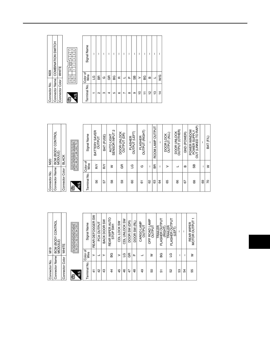
BCM (BODY CONTROL MODULE)
BCS-47
< WIRING DIAGRAM >
C
D
E
F
G
H
I
J
K
L
B
A
O
P
N
ABMIA5574GB