Nissan March K13. Manual - part 676
DIAGNOSIS SYSTEM (IPDM E/R)
WW-21
< SYSTEM DESCRIPTION >
C
D
E
F
G
H
I
J
K
M
A
B
WW
N
O
P
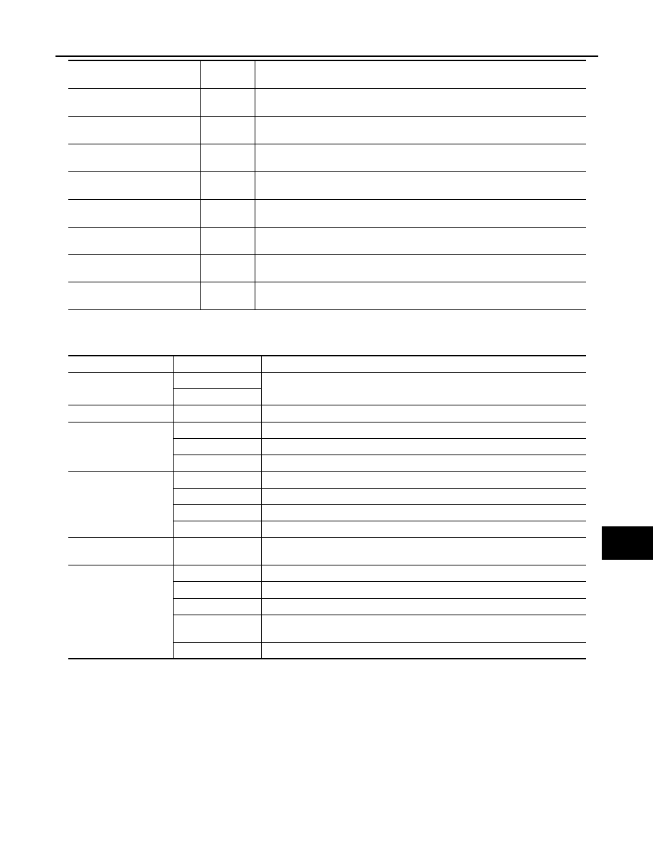
ACTIVE TEST
Test item
WITHOUT INTELLIGENT KEY
WITHOUT INTELLIGENT KEY : Diagnosis Description
INFOID:0000000006067182
AUTO ACTIVE TEST
Description
In auto active test, the IPDM E/R sends a drive signal to the following systems to check their operation.
• Oil pressure warning lamp
• Front wiper (LO, HI)
• Parking lamps
• License plate lamps
S/L RLY -REQ
[Off/On]
Displays the status of the steering lock relay signal received from BCM via CAN
communication.
S/L STATE
[LOCK/UNLK/UNKWN]
Displays the status of the steering lock judged by IPDM E/R.
DTRL REQ
[Off/On]
NOTE:
This item is indicated, but not monitored.
OIL P SW
[Open/Close]
Displays the status of the oil pressure switch judged by IPDM E/R.
HOOD SW
[Off/On]
NOTE:
This item is indicated, but not monitored
HL WASHER REQ
[Off/On]
NOTE:
This item is indicated, but not monitored.
THFT HRN REQ
[Off/On]
Displays the status of the theft warning horn request signal received from BCM via
CAN communication.
HORN CHIRP
[Off/On]
NOTE:
This item is indicated, but not monitored.
Monitor Item
[Unit]
MAIN SIG-
NALS
Description
Test item
Operation
Description
CORNERING LAMP
LH
NOTE:
This item is indicated, but cannot be tested.
RH
HORN
On
Operates horn relay for 20 ms.
FRONT WIPER
Off
OFF
Lo
Operates the front wiper relay.
Hi
Operates the front wiper relay and front wiper high relay.
MOTOR FAN
1
OFF
2
Operates the cooling fan relay (LO operation).
3
Operates the cooling fan relay (MID operation).
4
Operates the cooling fan relay (HI operation).
HEAD LAMP WASHER
Off
NOTE:
This item is indicated, but cannot be tested.
EXTERNAL LAMPS
Off
OFF
TAIL
Operates the tail lamp relay.
Lo
Operates the headlamp low relay.
Hi
Operates the headlamp low relay and ON/OFF the headlamp high relay at 1 sec-
ond intervals.
Fog
Operates the front fog lamp relay.