Nissan March K13. Manual - part 635
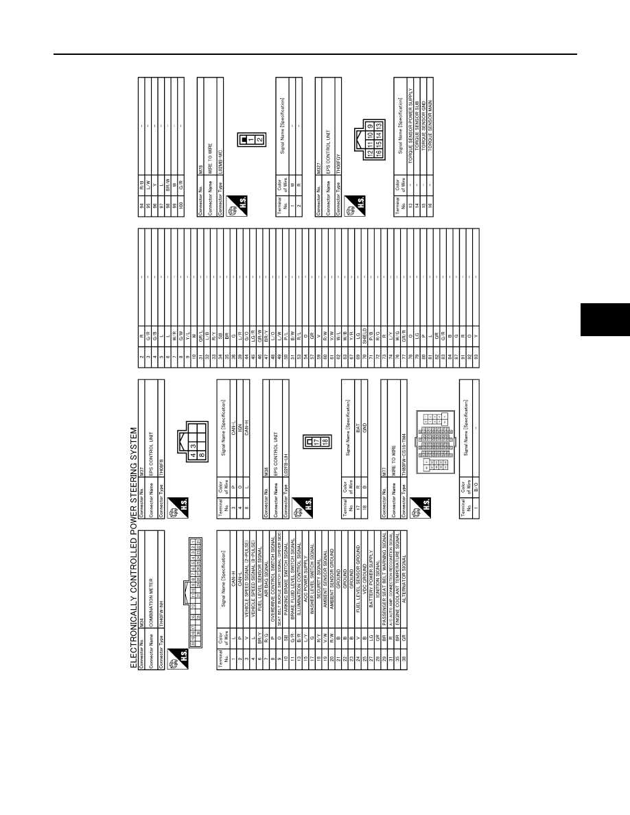
ELECTRONICALLY CONTROLLED POWER STEERING SYSTEM
STC-15
< WIRING DIAGRAM >
C
D
E
F
H
I
J
K
L
M
A
B
STC
N
O
P
JCGWM0283GB
|
|
|
ELECTRONICALLY CONTROLLED POWER STEERING SYSTEM STC-15 < WIRING DIAGRAM > C D E F H I J K L M A B STC N O P JCGWM0283GB |