Nissan March K13. Manual - part 597
NATS ANTENNA AMP.
SEC-127
< REMOVAL AND INSTALLATION >
[WITH INTELLIGENT KEY SYSTEM]
C
D
E
F
G
H
I
J
L
M
A
B
SEC
N
O
P
REMOVAL AND INSTALLATION
NATS ANTENNA AMP.
Removal and Installation
INFOID:0000000006038647
REMOVAL
1.
Remove the push-button ignition switch. Refer to
SEC-128, "Removal and Installation"
.
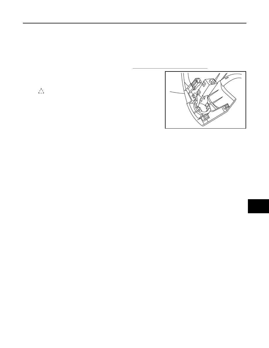
2.
Disengage the NATS antenna amp. pawl, and then remove
NATS antenna amp.
INSTALLATION
Install in the reverse order of removal.
: Pawl
JMKIA5307ZZ