Nissan March K13. Manual - part 585


  Index      Nissan     Nissan March K13 - Service and Repair Manual)


Search            


Content   ..  583  584  585  586   ..


Nissan March K13. Manual - part 585


B2608 STARTER RELAY

SEC-79

< DTC/CIRCUIT DIAGNOSIS >

[WITH INTELLIGENT KEY SYSTEM]

C

D

E

F

G

H

I

J

L

M

A

B

SEC

N

O

P

4.

Check continuity between starter relay harness connector and BCM harness connector.

5.

Check continuity between IPDM E/R harness connector and ground.

Is the inspection result normal?

YES

>> Replace IPDM E/R. Refer to 

BCS-57, "Removal and Installation"

.

NO

>> Repair or replace harness.

4.

CHECK STARTER RELAY

Refer to 

SEC-79, "Component Inspection"

.

Is the inspection result normal?

YES

>> GO TO 5.

NO

>> Replace starter relay.

5.

CHECK INTERMITTENT INCIDENT

Refer to 

GI-33, "Intermittent Incident"

.

>> INSPECTION END

Component Inspection

INFOID:0000000006044327

1.

CHECK STARTER RELAY

1.

Turn ignition switch OFF.

2.

Disconnect starter relay.

3.

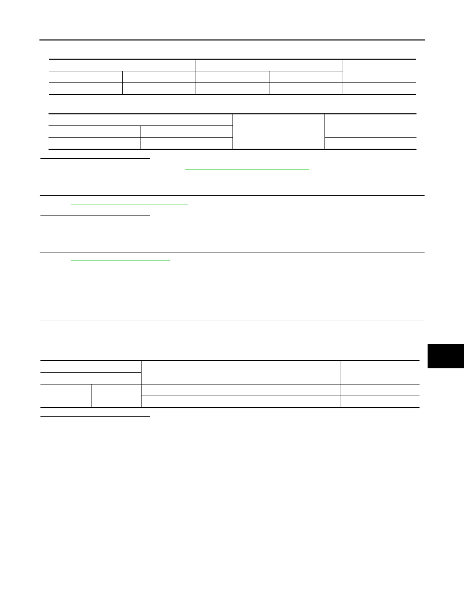
Check continuity between starter relay terminals.

Is the inspection result normal?

YES

>> INSPECTION END

NO

>> Replace starter relay.

Starter relay

BCM

Continuity

Connector

Terminal

Connector

Terminal

E60

1

M71

97

Existed

Starter relay

Ground

Continuity

Connector

Terminal

E60

1

Not existed

Starter relay

Condition

Continuity

Terminal

3

5

12 V direct current supply between terminals 1 and 2

Existed

No current supply

Not existed

SEC-80

< DTC/CIRCUIT DIAGNOSIS >

[WITH INTELLIGENT KEY SYSTEM]

B2609 STEERING STATUS

B2609 STEERING STATUS

DTC Logic

INFOID:0000000006038551

DTC DETECTION LOGIC

DTC CONFIRMATION PROCEDURE

1.

PERFORM DTC CONFIRMATION PROCEDURE 1

1.

Press push-button ignition switch under the following conditions and wait 1 second or more.

-

Selector lever: In the P position

-

Brake pedal: Not depressed

2.

Check DTC in “Self Diagnostic Result” mode of “BCM” using CONSULT-III.

Is DTC detected?

YES

>> Go to 

SEC-80, "Diagnosis Procedure"

.

NO

>> GO TO 2.

2.

PERFORM DTC CONFIRMATION PROCEDURE 2

1.

Turn ignition switch ON.

2.

Turn ignition switch OFF.

3.

Press driver side door switch and wait 1 second or more.

4.

Check DTC in “Self Diagnostic Result” mode of “BCM” using CONSULT-III.

Is DTC detected?

YES

>> Go to 

SEC-80, "Diagnosis Procedure"

.

NO

>> INSPECTION END

Diagnosis Procedure

INFOID:0000000006038552

1.

CHECK IPDM E/R INPUT SIGNAL

1.

Turn ignition switch OFF.

2.

Check voltage between IPDM E/R harness connector and ground.

NOTE:

Is the inspection result normal?

YES

>> GO TO 3.

DTC No.

Trouble diagnosis name

DTC detecting condition

Possible cause

B2609

S/L STATUS

BCM detects one of the following status.
• Combination of steering lock state switch and 

steering unlock state switch is not normal.

• Combination of steering lock state switch and 

steering unlock state switch is different from 
steering lock/unlock state that BCM recognizes.

• Harness or connectors

(Steering lock unit circuit is open or 
shorted.)

• Steering lock unit 
• BCM

(+)

(–)

Condition

Voltage (V)

(Approx.)

IPDM E/R

Connector

Terminal

E17

88

Ground

Steering lock unit

Unlock

12

Lock

0

89

Unlock

0

Lock

12

To lock the steering

1.

Set the selector lever in the P position.

2.

Turn the power supply position to the OFF position.

3.

Press any door switch.

To unlock the steering

1.

Set the selector lever in the P position.

2.

Press the push-button ignition switch with brake pedal not depressed.

B2609 STEERING STATUS

SEC-81

< DTC/CIRCUIT DIAGNOSIS >

[WITH INTELLIGENT KEY SYSTEM]

C

D

E

F

G

H

I

J

L

M

A

B

SEC

N

O

P

NO

>> GO TO 2.

2.

CHECK IPDM E/R INPUT SIGNAL CIRCUIT

1.

Disconnect IPDM E/R connector and steering lock unit connector.

2.

Check continuity between IPDM E/R harness connector and steering lock unit harness connector.

3.

Check continuity between IPDM E/R harness connector and ground.

Is the inspection result normal?

YES

>> Replace steering lock unit.

NO

>> Repair or replace harness.

3.

CHECK BCM INPUT SIGNAL

1.

Turn ignition switch OFF.

2.

Check voltage between BCM harness connector and ground.

NOTE:

Is the inspection result normal?

YES

>> Replace BCM. Refer to 

BCS-57, "Removal and Installation"

.

NO

>> GO TO 4.

4.

CHECK BCM INPUT SIGNAL CIRCUIT

1.

Disconnect BCM connector and steering lock unit connector.

2.

Check continuity between BCM harness connector and steering lock unit harness connector.

3.

Check continuity between BCM harness connector and ground.

IPDM E/R

Steering lock unit

Continuity

Connector

Terminal

Connector

Terminal

E17

88

M12

3

Existed

89

8

IPDM E/R

Ground

Continuity

Connector

Terminal

E17

88

Not existed

89

(+)

(–)

Condition

Voltage (V)

(Approx.)

BCM

Connector

Terminal

M71

107

Ground

Steering lock unit

Lock

0

Unlock

12

108

Lock

12

Unlock

0

To lock the steering

1.

Set the selector lever in the P position.

2.

Turn the power supply position to the OFF position.

3.

Press any door switch.

To unlock the steering

1.

Set the selector lever in the P position.

2.

Press the push-button ignition switch with brake pedal not depressed.

BCM

Steering lock unit

Continuity

Connector

Terminal

Connector

Terminal

M71

107

M12

3

Existed

108

8

SEC-82

< DTC/CIRCUIT DIAGNOSIS >

[WITH INTELLIGENT KEY SYSTEM]

B2609 STEERING STATUS

Is the inspection result normal?

YES

>> Replace steering lock unit.

NO

>> Repair or replace harness.

BCM

Ground

Continuity

Connector

Terminal

M71

107

Not existed

108


Content   ..  583  584  585  586   ..