Nissan March K13. Manual - part 569


  Index      Nissan     Nissan March K13 - Service and Repair Manual)


Search            


Content   ..  567  568  569  570   ..


Nissan March K13. Manual - part 569


SYSTEM

SEC-15

< SYSTEM DESCRIPTION >

[WITH INTELLIGENT KEY SYSTEM]

C

D

E

F

G

H

I

J

L

M

A

B

SEC

N

O

P

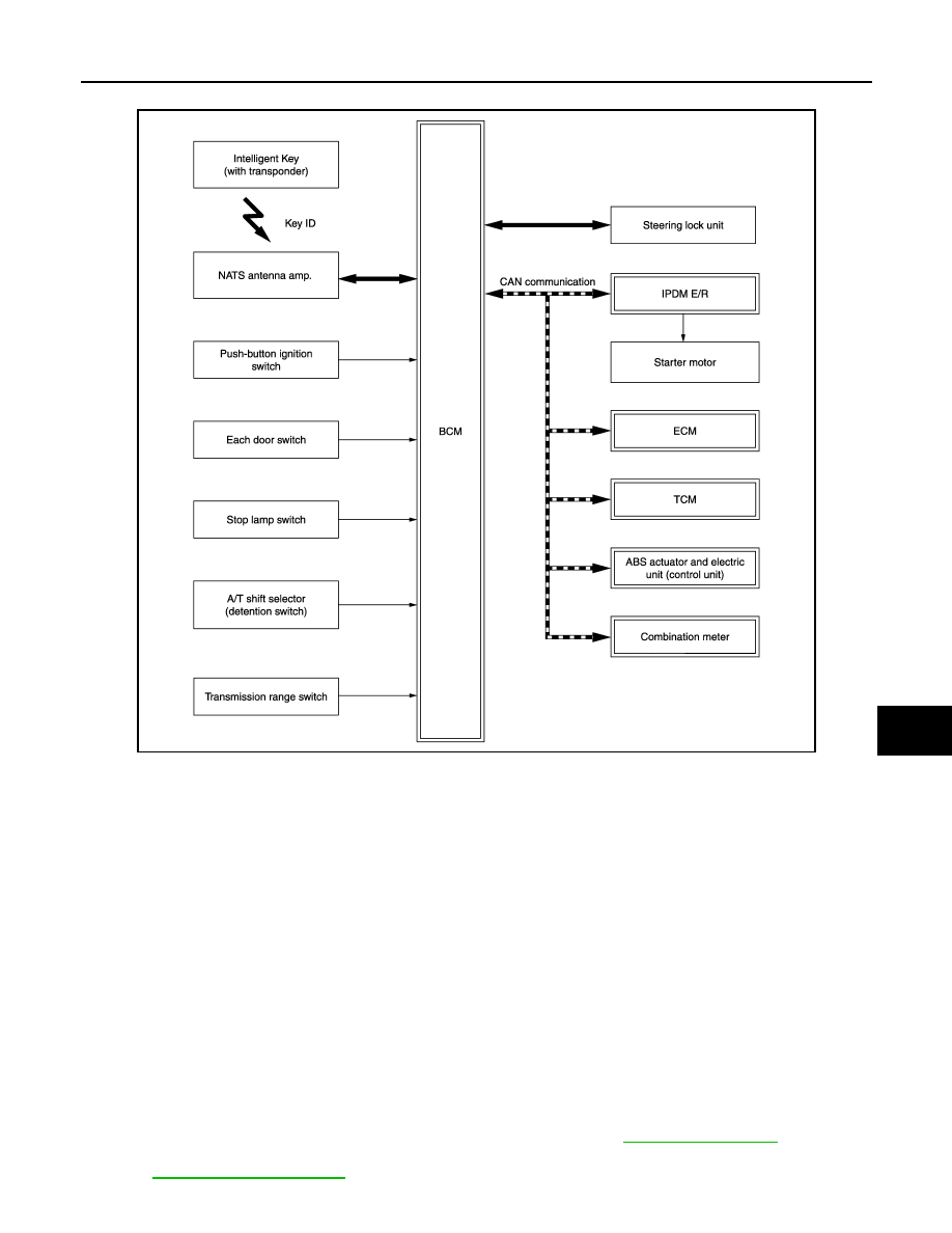
NISSAN ANTI-THEFT SYSTEM : System Diagram

INFOID:0000000006038487

NISSAN ANTI-THEFT SYSTEM : System Description

INFOID:0000000006038488

SYSTEM DESCRIPTION

• The Nissan Anti-Theft System (NATS) prevents the engine from being started by Intelligent Key whose ID is

not registered to the vehicle (BCM). It has higher protection against auto theft involving the duplication of
mechanical keys.

• The ignition key integrated in the Intelligent Key cannot start the engine. When the Intelligent Key battery is

discharged, the NATS ID verification is performed between the transponder integrated with Intelligent Key
and BCM via NATS antenna amp. when the Intelligent Key backside is contacted to push-button ignition
switch. If the verification result is OK, the engine start operation can be performed by the push-button igni-
tion switch operation.

• Locate the security indicator lamp and apply the anti-theft system equipment sticker that warns that the Nis-

san Anti-Theft System (NATS) is on board the model.

• Security indicator lamp always blinks when the power supply position is in any position except the ON posi-

tion.

• Up to 4 Intelligent Keys can be registered (including the standard ignition key) upon request from the owner.
• Specified registration is required when replacing ECM, BCM or Intelligent Key. For the registration proce-

dures, refer to CONSULT-III Operation Manual NATS-IVIS/NVIS.

• When NATS has a malfunction, engine may not start. However, the engine can not be started because of

other than NATS malfunction, so start  the trouble diagnosis according to 

SEC-33, "Work Flow"

.

• If ECM other than genuine part is installed, the engine cannot be started. For ECM replacement procedure,

refer to 

EC-376, "Work Procedure"

 [HR12DE (TYPE 2)].

JMKIA5374GB

SEC-16

< SYSTEM DESCRIPTION >

[WITH INTELLIGENT KEY SYSTEM]

SYSTEM

PRECAUTIONS FOR KEY REGISTRATION

• The ID registration is a procedure that erases the current NATS ID once, and then reregisters a new ID.

Therefore before starting the registration operation, collect all registered Intelligent Keys from the customer.

• When registering the Intelligent Key, perform only one procedure to simultaneously register both ID (NATS

ID and Intelligent Key ID).

SECURITY INDICATOR LAMP

• Security indicator lamp warns that the vehicle is equipped with NATS.
• Security indicator lamp always blinks when the power supply position is in any position except the ON posi-

tion.
NOTE:
Because security indicator lamp is highly efficient, the battery is barely affected.

ENGINE START OPERATION WHEN INTELLIGENT KEY IS CONTACTED TO PUSH-BUTTON IG-
NITION SWITCH

1.

When brake pedal is depressed while selector lever is in the P position, BCM activates NATS antenna
amp. that is located behind push-button ignition switch.

2.

When Intelligent Key (transponder built-in) backside is contacted to push-button ignition switch, BCM
starts NATS ID verification between BCM and Intelligent Key (transponder built-in) via NATS antenna
amp.

3.

When NATS ID verification result is OK, buzzer in combination meter sounds and BCM transmits the
result to ECM.

4.

When push-button ignition switch is pressed, BCM transmits steering unlock signal to steering lock unit
and IPDM E/R.

5.

IPDM E/R turns steering lock relay ON and supplies power supply to the steering lock unit.

6.

The steering lock is released.

7.

BCM transmits the power supply stop signal to IPDM E/R when detecting that the steering lock is in the
unlock position.

8.

IPDM E/R turns steering lock relay OFF and stops power supply to the steering lock unit.

9.

BCM turns ACC relay ON and transmits ignition power supply ON signal to IPDM E/R.

10. IPDM E/R turns the ignition relay ON and starts the ignition power supply.

11. BCM detects that the selector lever position is P or N.
12. BCM transmits starter request signal to IPDM E/R and turns the starter relay in IPDM E/R ON if BCM

judges that the engine start condition* is satisfied.

13. IPDM E/R turns the starter control relay ON when receiving the starter request signal.
14. Power supply is supplied through the starter relay and the starter control relay to operate the starter motor.

15. When BCM receives feedback signal from ECM indicating that the engine is started, BCM transmits a

stop signal to IPDM E/R and stops cranking by turning off the starter motor relay. (If engine start is unsuc-
cessful, cranking stops automatically within 5 seconds.)

*: For the engine start condition, refer to “POWER SUPPLY POSITION CHANGE TABLE BY PUSH-BUTTON
IGNITION SWITCH OPERATION” below.

POWER SUPPLY POSITION CHANGE TABLE BY PUSH-BUTTON IGNITION SWITCH OPERA-
TION

The power supply position changing operation can be performed with the following operations.
NOTE:
• When an Intelligent Key is within the detection area of inside key antenna and when Intelligent Key backside

is contacted to push-button ignition switch, it is equivalent to the operations below.

• When starting the engine, the BCM monitors under the engine start conditions,
- Brake pedal operating condition
- Selector lever position
- Vehicle speed

Vehicle speed: less than 4 km/h (2.5 MPH)

SYSTEM

SEC-17

< SYSTEM DESCRIPTION >

[WITH INTELLIGENT KEY SYSTEM]

C

D

E

F

G

H

I

J

L

M

A

B

SEC

N

O

P

Vehicle speed: 4 km/h (2.5 MPH) or more

Emergency stop operation

• Press and hold the push-button ignition switch for 2 seconds or more.

• Press the push-button ignition switch 3 times or more within 1.5 seconds.

Power supply position

Engine start/stop condition

Push-button ignition switch 

operation frequency

Selector lever

Brake pedal operation 

condition

LOCK 

 ACC

Not depressed

1

LOCK 

 ACC 

 ON

Not depressed

2

LOCK 

 ACC 

 ON 

 OFF

Not depressed

3

LOCK 

 START

ACC 

 START

ON 

 START

P or N position

Depressed

1

Engine is running 

 OFF

1

Power supply position

Engine start/stop condition

Push-button ignition switch 

operation frequency

Selector lever

Brake pedal operation 

condition

Engine is running 

 ACC 

Emergency stop operation

Engine stall return operation while 
driving 

N position

Not depressed

1

SEC-18

< SYSTEM DESCRIPTION >

[WITH INTELLIGENT KEY SYSTEM]

DIAGNOSIS SYSTEM (BCM)

DIAGNOSIS SYSTEM (BCM)

COMMON ITEM

COMMON ITEM : CONSULT-III Function (BCM - COMMON ITEM)

INFOID:0000000006046710

APPLICATION ITEM

CONSULT-III performs the following functions via CAN communication with BCM.

SYSTEM APPLICATION

BCM can perform the following functions for each system.
NOTE:
It can perform the diagnosis modes except the following for all sub system selection items.

×

: Applicable item

*: This item is displayed, but is not used.

FREEZE FRAME DATA (FFD)

The BCM records the following vehicle condition at the time a particular DTC is detected, and displays on
CONSULT-III.

Diagnosis mode

Function Description

Work Support

Changes the setting for each system function.

Self Diagnostic Result

Displays the diagnosis results judged by BCM.

CAN Diag Support Monitor

Monitors the reception status of CAN communication viewed from BCM. Refer to CONSULT-III opera-
tion manual.

Data Monitor

The BCM input/output signals are displayed.

Active Test

The signals used to activate each device are forcibly supplied from BCM.

Ecu Identification

The BCM part number is displayed.

Configuration

• Read and save the vehicle specification.
• Write the vehicle specification when replacing BCM.

System

Sub system selection item

Diagnosis mode

Work Support

Data Monitor

Active Test

Door lock

DOOR LOCK

×

×

×

Rear window defogger

REAR DEFOGGER

×

×

Warning chime

BUZZER

×

×

Interior room lamp timer

INT LAMP

×

×

×

Exterior lamp

HEAD LAMP

×

×

×

Wiper and washer

WIPER

×

×

×

Turn signal and hazard warning lamps

FLASHER

×

×

×

Automatic air conditioner

AIR CONDITONER

×

×

• Intelligent Key system
• Engine start system

INTELLIGENT KEY

×

×

×

Combination switch

COMB SW

×

Body control system

BCM

×

NATS

IMMU

×

×

×

Interior room lamp battery saver

BATTERY SAVER

×

×

×

Back door

TRUNK

×

THEFT ALM*

×

×

×

RETAINED PWR*

×

Signal buffer system

SIGNAL BUFFER

×

×


Content   ..  567  568  569  570   ..