Nissan March K13. Manual - part 567
COMPONENT PARTS
SEC-7
< SYSTEM DESCRIPTION >
[WITH INTELLIGENT KEY SYSTEM]
C
D
E
F
G
H
I
J
L
M
A
B
SEC
N
O
P
SYSTEM DESCRIPTION
COMPONENT PARTS
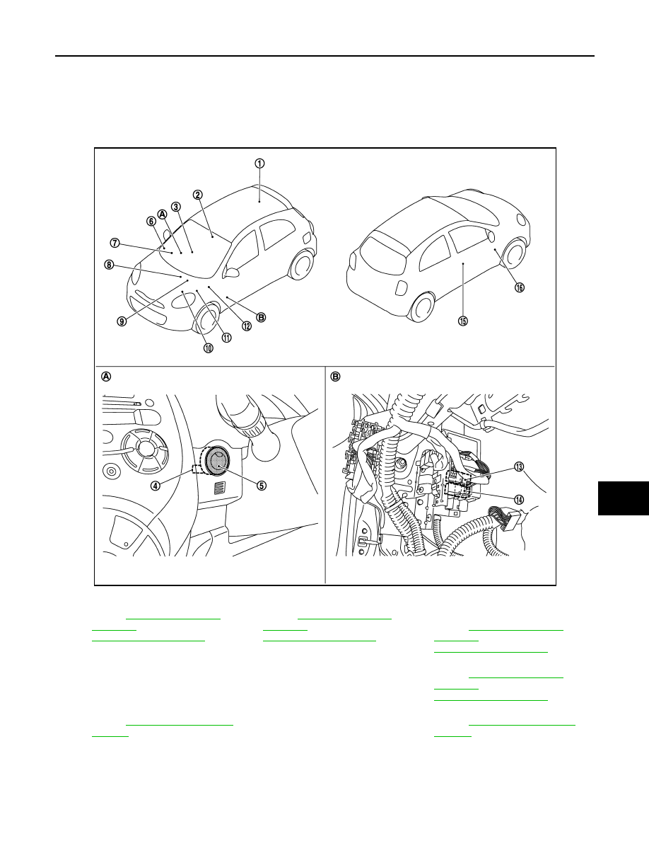
Component Parts Location
INFOID:0000000006038458
1.
Inside key antenna (luggage room)
Refer to
SYSTEM :
Component Parts Location"
.
2.
Inside key antenna (console)
Refer to
SYSTEM :
Component Parts Location"
.
3.
Inside key antenna (instrument cen-
ter)
Refer to
SYSTEM :
Component Parts Location"
4.
NATS antenna amp.
5.
Push-button ignition switch
6.
Remote keyless entry receiver
Refer to
SYSTEM :
Component Parts Location"
7.
.
8.
ABS actuator and electric unit (con-
trol unit)
Refer to BRC section.
9.
IPDM E/R
Refer to
JMKIA5375ZZ