Nissan March K13. Manual - part 502


  Index      Nissan     Nissan March K13 - Service and Repair Manual)


Search            


Content   ..  500  501  502  503   ..


Nissan March K13. Manual - part 502


PCS-90

< DTC/CIRCUIT DIAGNOSIS >

[POWER DISTRIBUTION SYSTEM]

PUSH-BUTTON IGNITION SWITCH POSITION INDICATOR

PUSH-BUTTON IGNITION SWITCH POSITION INDICATOR

Description

INFOID:0000000005998942

Push-button ignition switch changes the power supply position.
BCM maintains the power supply position status.
BCM changes the power supply position with the operation of the push-button ignition switch.

Component Function Check

INFOID:0000000005998943

1.

CHECK FUNCTION

Check push-button ignition switch (“PUSH SWITCH INDICATOR”) in Active Test Mode with CONSULT-III.

Is the inspection result normal?

YES

>> INSPECTION END

NO

>> Refer to 

PCS-90, "Diagnosis Procedure"

.

Diagnosis Procedure

INFOID:0000000005998944

1.

CHECK PUSH-BUTTON IGNITION SWITCH INPUT SIGNAL

1.

Turn ignition switch OFF.

2.

Disconnect push-button ignition switch connector.

3.

Check voltage between push-button ignition switch harness connector and ground.

Is the inspection normal?

YES

>> GO TO 2.

NO-1

>> Check 10 A fuse [No.7, located in fuse block (J/B)].

NO-2

>> Check harness for open or short between push-button ignition switch and fuse.

2.

CHECK BCM INPUT

1.

Connect push-button ignition switch connector.

2.

Disconnect BCM connector.

3.

Check voltage between BCM connector and ground.

Is the inspection normal?

YES

>> Replace BCM. Refer to 

BCS-57, "Removal and Installation"

.

NO

>> GO TO 3.

3.

CHECK PUSH-BUTTON IGNITION SWITCH CIRCUIT

1.

Disconnect push-button ignition switch connector.

2.

Check continuity between BCM harness connector and push-button ignition switch harness connector.
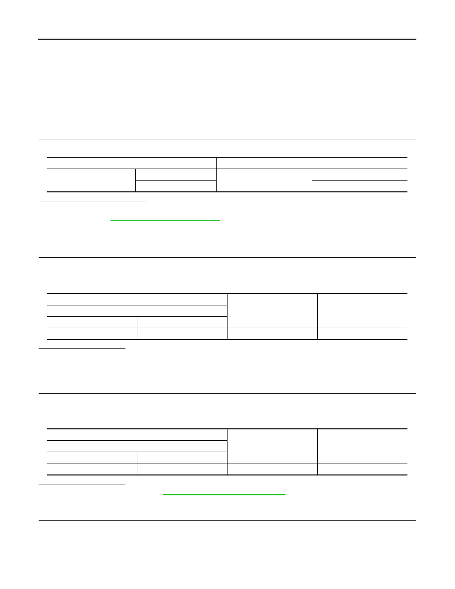
Test item

Description

PUSH SWITCH INDICATOR

ON

Position indicator

 Illuminates

OFF

Does not illuminate

(+)

(–)

Voltage (V)

(Approx.)

Push-button ignition switch

Connector

Terminal

M101

3

Ground

Battery voltage

(+)

(–)

Voltage (V)

(Approx.)

BCM

Connector

Terminal

M71

91

Ground

Battery voltage

PCS

PUSH-BUTTON IGNITION SWITCH POSITION INDICATOR

PCS-91

< DTC/CIRCUIT DIAGNOSIS >

[POWER DISTRIBUTION SYSTEM]

C

D

E

F

G

H

I

J

K

L

B

A

O

P

N

3.

Check continuity between BCM harness connector and ground.

Is the inspection normal?

YES

>> Replace push-button ignition switch.

NO

>> Repair or replace harness.

BCM

Push-button ignition switch

Continuity

Connector

Terminal

Connector

Terminal

M71

91

M101

7

Existed

BCM

Ground

Continuity

Connector

Terminal

M71

91

Not existed

PCS-92

< SYMPTOM DIAGNOSIS >

[POWER DISTRIBUTION SYSTEM]

PUSH-BUTTON IGNITION SWITCH DOES NOT OPERATE

SYMPTOM DIAGNOSIS

PUSH-BUTTON IGNITION SWITCH DOES NOT OPERATE

Description

INFOID:0000000005998945

Check that vehicle is under the condition shown in “Conditions of vehicle” before starting diagnosis, and check
each symptom.
NOTE:
The engine start function, door lock function, power distribution system, and NATS-IVIS/NVIS in the Intelligent
Key system are closely related to each other regarding control. The vehicle security function can operate only
when the door lock and power distribution system are operating normally.

Conditions of Vehicle (Operating Conditions)

• “ENGINE START BY I-KEY” in “WORK SUPPORT” is ON when setting on CONSULT-III.
• One or more of Intelligent Keys with registered Intelligent Key ID is in the vehicle.

Diagnosis Procedure

INFOID:0000000005998946

1.

PERFORM WORK SUPPORT

Perform “INSIDE ANT DIAGNOSIS” on Work Support of “INTELLIGENT KEY”.
Refer to 

XX-XX, "*****"

.

>> GO TO 2.

2.

PERFORM SELF-DIAGNOSIS RESULT

Perform Self-Diagnosis Result of “BCM”.

Is DTC detected?

YES

>> Refer to 

BCS-40, "DTC Index"

.

NO

>> GO TO 3.

3.

CHECK PUSH-BUTTON IGNITION SWITCH

Check push-button ignition switch.
Refer to 

PCS-87, "Component Function Check"

.

Is the operation normal?

YES

>> GO TO 4.

NO

>> Repair or replace malfunctioning parts.

4.

CONFIRM THE OPERATION

Confirm the operation again.

Is the inspection normal?

YES

>> Check intermittent incident. Refer to 

GI-33, "Intermittent Incident"

.

NO

>> GO TO 1.

PCS

PUSH-BUTTON IGNITION SWITCH POSITION INDICATOR DOES NOT ILLUMI-

NATE

PCS-93

< SYMPTOM DIAGNOSIS >

[POWER DISTRIBUTION SYSTEM]

C

D

E

F

G

H

I

J

K

L

B

A

O

P

N

PUSH-BUTTON IGNITION SWITCH POSITION INDICATOR DOES NOT IL-
LUMINATE

Description

INFOID:0000000005998947

• Before performing the diagnosis in the following table, check “Work Flow”. Refer to 

PCS-68, "Work Flow"

.

• Check that vehicle is under the condition shown in “Conditions of vehicle” before starting diagnosis, and

check each symptom.

Conditions of Vehicle (Operating Conditions)

• “ENGINE START BY I-KEY” in “WORK SUPPORT” is ON when setting on CONSULT-III.
• One or more of Intelligent Keys with registered Intelligent Key ID is in the vehicle.

Diagnosis Procedure

INFOID:0000000005998948

1.

CHECK PUSH-BUTTON IGNITION SWITCH INDICATOR

Check push-button ignition switch indicator.
Refer to 

PCS-90, "Component Function Check"

.

Is the inspection result normal?

YES

>> GO TO 2.

NO

>> Repair or replace the malfunctioning parts.

2.

CONFIRM THE OPERATION

Confirm the operation again.

Is the result normal?

YES

>> Check intermittent incident. Refer to 

GI-33, "Intermittent Incident"

.

NO

>> GO TO 1.


Content   ..  500  501  502  503   ..