Nissan March K13. Manual - part 481
PCS-6
< SYSTEM DESCRIPTION >
[IPDM E/R (WITH I-KEY)]
SYSTEM
SYSTEM
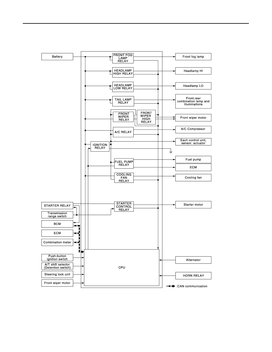
RELAY CONTROL SYSTEM
RELAY CONTROL SYSTEM : System Diagram
INFOID:0000000005914113
RELAY CONTROL SYSTEM : System Description
INFOID:0000000005914114
IPDM E/R activates the internal control circuit to perform the relay ON-OFF control according to the input sig-
nals from various sensors and the request signals received from control units via CAN communication.
CAUTION:
IPDM E/R integrated relays cannot be removed.
JMMIA0352GB