Nissan March K13. Manual - part 479
PARKING BRAKE CONTROL
PB-3
< REMOVAL AND INSTALLATION >
C
D
E
G
H
I
J
K
L
M
A
B
PB
N
O
P
REMOVAL AND INSTALLATION
PARKING BRAKE CONTROL
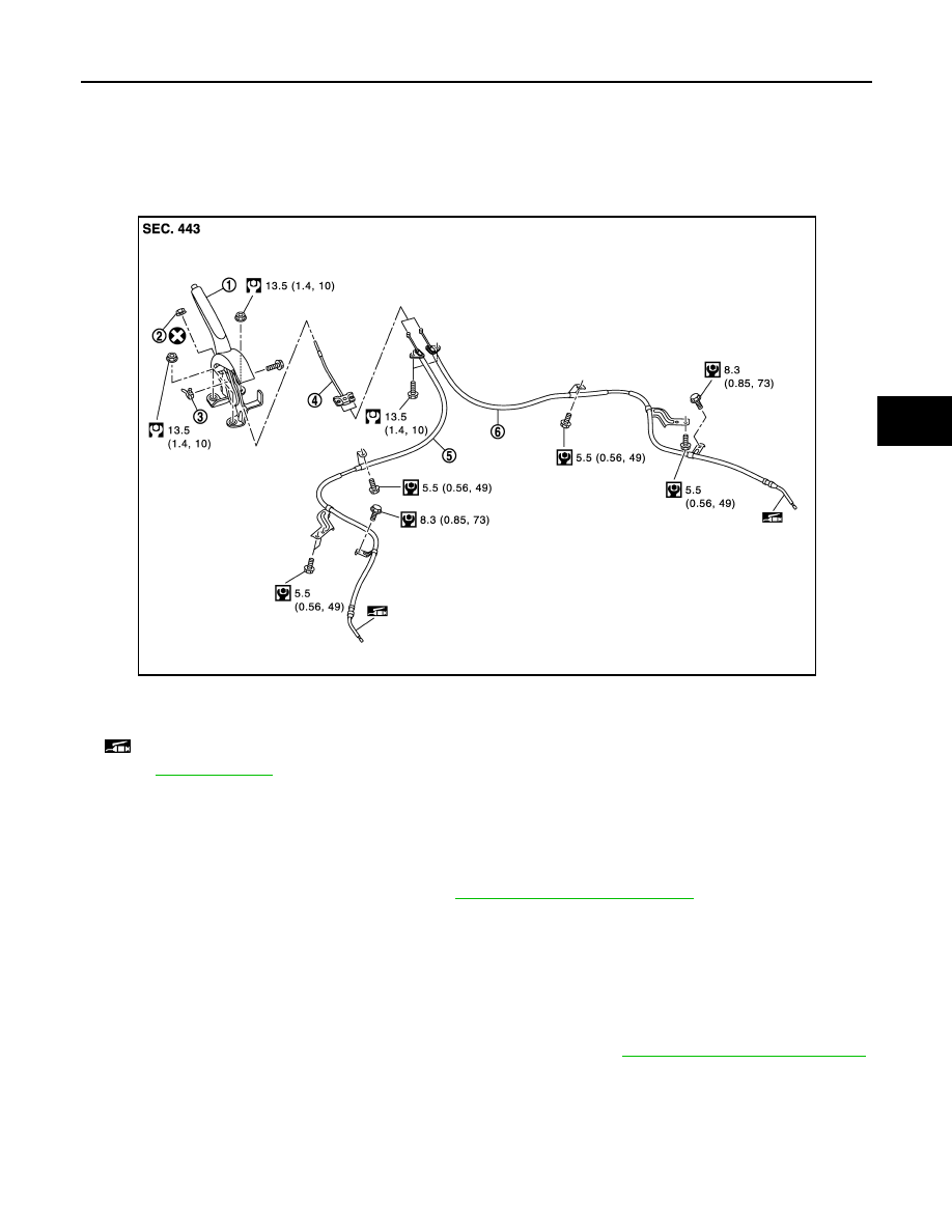
Exploded View
INFOID:0000000006037610
Removal and Installation
INFOID:0000000006037611
REMOVAL
1.
Remove rear tires.
2.
Remove the center console assembly. Refer to
IP-21, "Removal and Installation"
3.
Disconnect the parking brake switch harness connector.
4.
Remove adjusting nut and loosen front cable.
5.
Separate the rear cable from the front cable.
6.
Remove the parking brake lever assembly and front cable.
7.
Remove the front cable from parking brake lever assembly.
8.
Remove the parking brake switch from parking brake lever assembly.
9.
Remove brake shoe, and remove rear cable from brake shoe. Refer to
BR-39, "Removal and Installation"
.
10. Remove rear cable mounting bolts, and remove rear cable.
INSTALLATION
Note the following, install in the reverse order of the removal.
• Never reuse adjusting nut.
1.
Parking brake lever assembly
2.
Adjusting nut
3.
Parking brake switch
4.
Front cable
5.
Rear cable (LH)
6.
Rear cable (RH)
: Apply multi-purpose grease.
Refer to
for symbols not described on the above.
JPFIB0120GB