Nissan March K13. Manual - part 428


  Index      Nissan     Nissan March K13 - Service and Repair Manual)


Search            


Content   ..  426  427  428  429   ..


Nissan March K13. Manual - part 428


IP-22

< REMOVAL AND INSTALLATION >

CENTER CONSOLE ASSEMBLY
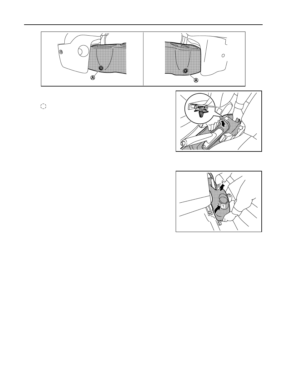
4.

Remove center console assembly fixing clips (A).

5.

Pull up center console assembly to disengage the clips.

6.

Disconnect harness connectors. (with Switches)

7.

Slide front seat RH to the rearmost position and operate to the fully reclining status.

8.

Slide front seat LH to the frontmost position and tilt seatback to the fully forward status.

9.

Lift up rear portion of center console assembly while rotating
and remove center console assembly.

INSTALLATION

Install in the reverse order of removal.

JMJIA3981ZZ

: Clip

JMJIA3982ZZ

JMJIA4077ZZ

LAN

LAN-1

ELECTRICAL & POWER CONTROL

C

D

E

F

G

H

I

J

K

L

B

SECTION 

LAN

A

O

P

N

CONTENTS

LAN SYSTEM

CAN FUNDAMENTAL

PRECAUTION ...............................................

3

PRECAUTIONS ...................................................

3

Precautions for Trouble Diagnosis  ............................

3

Precautions for Harness Repair  ................................

3

SYSTEM DESCRIPTION  ..............................

4

SYSTEM ..............................................................

4

CAN COMMUNICATION SYSTEM .............................

4

CAN COMMUNICATION SYSTEM : System De-
scription ...................................................................
..

4

CAN COMMUNICATION SYSTEM : System Dia-
gram ........................................................................
..

4

CAN COMMUNICATION SYSTEM : CAN Com-
munication Control Circuit  .......................................
..

5

DIAG ON CAN  .............................................................

5

DIAG ON CAN : Description  .....................................

5

DIAG ON CAN : System Diagram  .............................

6

TROUBLE DIAGNOSIS  ......................................

7

Condition of Error Detection ......................................

7

Symptom When Error Occurs in CAN Communi-
cation System ..........................................................
..

7

CAN Diagnosis with CONSULT-III  ..........................

10

Self-Diagnosis .........................................................

11

CAN Diagnostic Support Monitor  ............................

11

How to Use CAN Communication Signal Chart  ......

13

BASIC INSPECTION  ...................................

14

DIAGNOSIS AND REPAIR WORKFLOW  .........

14

Trouble Diagnosis Flow Chart  .................................

14

Trouble Diagnosis Procedure ..................................

14

CAN

HOW TO USE THIS MANUAL .....................

19

HOW TO USE THIS SECTION  .........................

19

Caution ....................................................................

19

Abbreviation List  ......................................................

19

PRECAUTION ..............................................

20

PRECAUTIONS .................................................

20

Precaution for Supplemental Restraint System 
(SRS) "AIR BAG" and "SEAT BELT PRE-TEN-
SIONER" .................................................................

20

Precautions for Trouble Diagnosis  ..........................

20

Precautions for Harness Repair  ..............................

20

SYSTEM DESCRIPTION  .............................

22

COMPONENT PARTS  ......................................

22

Component Parts Location  ......................................

22

SYSTEM ............................................................

23

CAN COMMUNICATION SYSTEM ............................

23

CAN COMMUNICATION SYSTEM : CAN System 
Specification Chart  ..................................................

23

CAN COMMUNICATION SYSTEM : CAN Com-
munication Signal Chart  ..........................................

23

WIRING DIAGRAM  ......................................

26

CAN SYSTEM  ...................................................

26

Wiring Diagram ........................................................

26

BASIC INSPECTION  ...................................

27

DIAGNOSIS AND REPAIR WORKFLOW  ........

27

Interview Sheet ........................................................

27

DTC/CIRCUIT DIAGNOSIS  .........................

28

MALFUNCTION AREA CHART ........................

28

Main Line  .................................................................

28

Branch Line  .............................................................

28

Short Circuit .............................................................

28

LAN-2

MAIN LINE BETWEEN IPDM-E AND DLC 
CIRCUIT .............................................................

29

Diagnosis Procedure  ..............................................

29

ECM BRANCH LINE CIRCUIT  ..........................

30

Diagnosis Procedure  ..............................................

30

ABS BRANCH LINE CIRCUIT  ..........................

31

Diagnosis Procedure  ..............................................

31

IPDM-E BRANCH LINE CIRCUIT  .....................

32

Diagnosis Procedure  ..............................................

32

TCM BRANCH LINE CIRCUIT  ..........................

33

Diagnosis Procedure  ..............................................

33

DLC BRANCH LINE CIRCUIT ...........................

34

Diagnosis Procedure  ..............................................

34

EPS BRANCH LINE CIRCUIT  ...........................

35

Diagnosis Procedure  ..............................................

35

M&A BRANCH LINE CIRCUIT  ..........................

36

Diagnosis Procedure  ..............................................

36

BCM BRANCH LINE CIRCUIT  ..........................

37

Diagnosis Procedure  ..............................................

37

CAN COMMUNICATION CIRCUIT ....................

38

Diagnosis Procedure  ..............................................

38

CAN SYSTEM (TYPE  2)

DTC/CIRCUIT DIAGNOSIS .........................

40

MAIN LINE BETWEEN IPDM-E AND DLC 
CIRCUIT .............................................................

40

Diagnosis Procedure  ..............................................

40

ECM BRANCH LINE CIRCUIT  ..........................

41

Diagnosis Procedure  ..............................................

41

IPDM-E BRANCH LINE CIRCUIT  .....................

42

Diagnosis Procedure  ..............................................

42

DLC BRANCH LINE CIRCUIT ...........................

43

Diagnosis Procedure  ..............................................

43

EPS BRANCH LINE CIRCUIT  ...........................

44

Diagnosis Procedure  ..............................................

44

M&A BRANCH LINE CIRCUIT  ..........................

45

Diagnosis Procedure  ..............................................

45

BCM BRANCH LINE CIRCUIT  ..........................

46

Diagnosis Procedure  ..............................................

46

CAN COMMUNICATION CIRCUIT ....................

47

Diagnosis Procedure  ..............................................

47

CAN SYSTEM (TYPE  3)

DTC/CIRCUIT DIAGNOSIS .........................

49

MAIN LINE BETWEEN IPDM-E AND DLC 
CIRCUIT .............................................................

49

Diagnosis Procedure ...............................................

49

ECM BRANCH LINE CIRCUIT  ..........................

50

Diagnosis Procedure ...............................................

50

IPDM-E BRANCH LINE CIRCUIT  .....................

51

Diagnosis Procedure ...............................................

51

TCM BRANCH LINE CIRCUIT  ..........................

52

Diagnosis Procedure ...............................................

52

DLC BRANCH LINE CIRCUIT  ..........................

53

Diagnosis Procedure ...............................................

53

EPS BRANCH LINE CIRCUIT ...........................

54

Diagnosis Procedure ...............................................

54

M&A BRANCH LINE CIRCUIT ..........................

55

Diagnosis Procedure ...............................................

55

BCM BRANCH LINE CIRCUIT ..........................

56

Diagnosis Procedure ...............................................

56

CAN COMMUNICATION CIRCUIT  ...................

57

Diagnosis Procedure ...............................................

57

CAN SYSTEM (TYPE  4)

DTC/CIRCUIT DIAGNOSIS ........................

59

MAIN LINE BETWEEN IPDM-E AND DLC 
CIRCUIT .............................................................

59

Diagnosis Procedure ...............................................

59

ECM BRANCH LINE CIRCUIT  ..........................

60

Diagnosis Procedure ...............................................

60

ABS BRANCH LINE CIRCUIT  ..........................

61

Diagnosis Procedure ...............................................

61

IPDM-E BRANCH LINE CIRCUIT  .....................

62

Diagnosis Procedure ...............................................

62

TCM BRANCH LINE CIRCUIT  ..........................

63

Diagnosis Procedure ...............................................

63

DLC BRANCH LINE CIRCUIT  ..........................

64

Diagnosis Procedure ...............................................

64

EPS BRANCH LINE CIRCUIT ...........................

65

Diagnosis Procedure ...............................................

65

M&A BRANCH LINE CIRCUIT ..........................

66

Diagnosis Procedure ...............................................

66

BCM BRANCH LINE CIRCUIT ..........................

67

Diagnosis Procedure ...............................................

67

CAN COMMUNICATION CIRCUIT  ...................

68

Diagnosis Procedure ...............................................

68

LAN

PRECAUTIONS

LAN-3

< PRECAUTION >

[CAN FUNDAMENTAL]

C

D

E

F

G

H

I

J

K

L

B

A

O

P

N

PRECAUTION

PRECAUTIONS

Precautions for Trouble Diagnosis

INFOID:0000000005908877

CAUTION:

• Never apply 7.0 V or more to the measurement terminal.
• Use a tester with open terminal voltage of 7.0 V or less.
• Turn the ignition switch OFF and disconnect the battery cable from the negative terminal when

checking the harness. 

Precautions for Harness Repair

INFOID:0000000005908878

• Solder the repaired area and wrap tape around the soldered area.

NOTE:
A fray of twisted lines must be within 110 mm (4.33 in).

• Bypass connection is never allowed at the repaired area.

NOTE:
Bypass connection may cause CAN communication error. The
spliced wire becomes separated and the characteristics of twisted
line are lost. 

• Replace the applicable harness as an assembly if error is detected on the shield lines of CAN communica-

tion line.

SKIB8766E

SKIB8767E


Content   ..  426  427  428  429   ..