Nissan March K13. Manual - part 341
GI-12
< HOW TO USE THIS MANUAL >
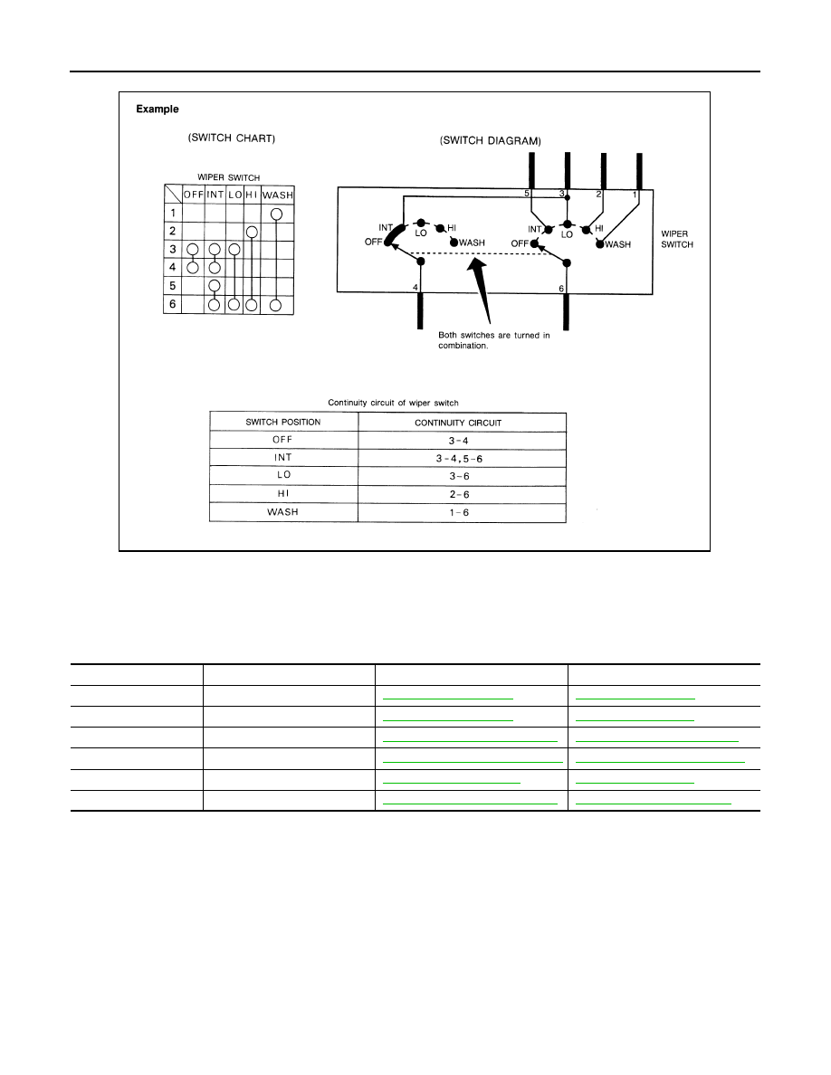
HOW TO READ WIRING DIAGRAMS
• The switch diagram is used in wiring diagrams.
Connector Information
INFOID:0000000006034280
CONNECTOR LIST
Connector information and harness layout are described in “POWER SUPPLY, GROUND & CIRCUIT ELE-
MENTS” Section.
JSAIA0017GB
Connector No.
Harness
Connector Information
Harness Layout
B
Body harness
D
Door harness
E
Engine room harness
PG-83, "E Engine Room Harness"
F
Engine control harness
PG-96, "F Engine Control Harness"
PG-38, "Engine Control Harness"
M
Main harness
R
Room lamp harness