Nissan March K13. Manual - part 299


  Index      Nissan     Nissan March K13 - Service and Repair Manual)


Search            


Content   ..  297  298  299  300   ..


Nissan March K13. Manual - part 299


EXL-22

< SYSTEM DESCRIPTION >

DIAGNOSIS SYSTEM (IPDM E/R) (WITH INTELLIGENT KEY SYSTEM)

Concept of Auto Active Test

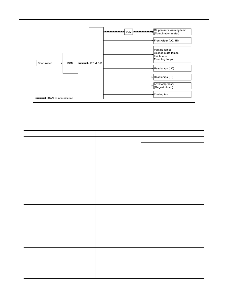
• IPDM E/R starts the auto active test with the door switch signals transmitted by BCM via CAN communica-

tion. Therefore, the CAN communication line between IPDM E/R and BCM is considered normal if the auto
active test starts successfully.

• The auto active test facilitates troubleshooting if any systems controlled by IPDM E/R cannot be operated.

Diagnosis Chart in Auto Active Test

JMMIA0354GB

Symptom

Inspection contents

Possible cause

Any of the following components do not operate

• Parking  lamps
• License plate lamps
• Tail lamps
• Front fog lamps
• Headlamps (HI, LO)
• Front wiper (HI, LO)

Perform auto active test.
Does the applicable system 
operate?

YES

BCM signal input circuit

NO

• Lamp or motor
• Lamp or motor ground circuit
• Harness or connector between 

IPDM E/R and applicable system

• IPDM  E/R

A/C compressor does not operate

Perform auto active test.
Does the magnet clutch oper-
ate?

YES

• BCM signal input circuit
• CAN communication signal be-

tween BCM and ECM

• CAN communication signal be-

tween ECM and IPDM E/R

NO

• Magnet clutch
• Harness or connector between 

IPDM E/R and magnet clutch

• IPDM  E/R

Oil pressure warning lamp does not operate

Perform auto active test.
Does the oil pressure warning 
lamp blink?

YES

• Harness or connector between 

IPDM E/R and oil pressure switch

• Oil pressure switch
• IPDM  E/R

NO

• CAN communication signal be-

tween IPDM E/R and BCM

• CAN communication signal be-

tween BCM and combination 
meter

• Combination meter

Cooling fan does not operate

Perform auto active test.
Does the cooling fan operate?

YES

• ECM signal input circuit
• CAN communication signal be-

tween ECM and IPDM E/R

NO

• Cooling fan motor
• Harness or connector between 

IPDM E/R and cooling fan motor

• IPDM  E/R

DIAGNOSIS SYSTEM (IPDM E/R) (WITH INTELLIGENT KEY SYSTEM)

EXL-23

< SYSTEM DESCRIPTION >

C

D

E

F

G

H

I

J

K

M

A

B

EXL

N

O

P

CONSULT-III Function (IPDM E/R)

INFOID:0000000006046539

APPLICATION ITEM

CONSULT-III performs the following functions via CAN communication with IPDM E/R.

SELF DIAGNOSTIC RESULT

Refer to 

PCS-22, "DTC Index"

.

DATA MONITOR

Monitor item

Diagnosis mode

Description

Ecu Identification

Allows confirmation of IPDM E/R part number.

Self Diagnostic Result

Displays the diagnosis results judged by IPDM E/R.

Data Monitor

Displays the real-time input/output data from IPDM E/R input/output data.

Active Test

IPDM E/R can provide a drive signal to electronic components to check their operations.

CAN Diag Support Monitor

The results of transmit/receive diagnosis of CAN communication can be read.

Monitor Item

[Unit]

MAIN SIG-

NALS

Description

MOTOR FAN REQ
[1/2/3/4]

×

Displays the value of the cooling fan speed request signal received from ECM via 
CAN communication.

AC COMP REQ
[Off/On]

×

Displays the status of the A/C compressor request signal received from ECM via 
CAN communication.

TAIL&CLR REQ
[Off/On]

×

Displays the status of the position light request signal received from BCM via CAN 
communication.

HL LO REQ
[Off/On]

×

Displays the status of the low beam request signal received from BCM via CAN 
communication.

HL HI REQ
[Off/On]

×

Displays the status of the high beam request signal received from BCM via CAN 
communication.

FR FOG REQ
[Off/On]

×

Displays the status of the front fog light request signal received from BCM via CAN 
communication.

FR WIP REQ
[Stop/1LOW/Low/Hi]

×

Displays the status of the front wiper request signal received from BCM via CAN 
communication.

WIP AUTO STOP
[STOP P/ACT P]

×

Displays the status of the front wiper stop position signal judged by IPDM E/R.

WIP PROT
[Off/BLOCK]

×

Displays the status of the front wiper fail-safe operation judged by IPDM E/R.

IGN RLY1 -REQ
[Off/On]

Displays the status of the ignition switch ON signal received from BCM via CAN 
communication.

IGN RLY
[Off/On]

×

Displays the status of the ignition relay judged by IPDM E/R.

PUSH SW
[Off/On]

Displays the status of the push-button ignition switch judged by IPDM E/R.

INTER/NP SW
[Off/On]

Displays the status of the shift position judged by IPDM E/R.

ST RLY CONT
[Off/On]

Displays the status of the starter relay status signal received from BCM via CAN 
communication.

IHBT RLY -REQ
[Off/On]

Displays the status of the starter control relay signal received from BCM via CAN 
communication.

ST/INHI RLY
[Off/ ST ON/INHI ON/UNKWN]

Displays the status of the starter relay and starter control relay judged by IPDM E/
R.

DETENT SW
[Off/On]

Displays the status of the A/T shift selector (detention switch) judged by IPDM E/
R.

EXL-24

< SYSTEM DESCRIPTION >

DIAGNOSIS SYSTEM (IPDM E/R) (WITH INTELLIGENT KEY SYSTEM)

ACTIVE TEST

Test item

S/L RLY -REQ
[Off/On]

Displays the status of the steering lock relay signal received from BCM via CAN 
communication.

S/L STATE
[LOCK/UNLK/UNKWN]

Displays the status of the steering lock judged by IPDM E/R.

DTRL REQ
[Off/On]

NOTE:
This item is indicated, but not monitored.

OIL P SW
[Open/Close]

Displays the status of the oil pressure switch judged by IPDM E/R.

HOOD SW
[Off/On]

NOTE:
This item is indicated, but not monitored

HL WASHER REQ
[Off/On]

NOTE:
This item is indicated, but not monitored.

THFT HRN REQ
[Off/On]

Displays the status of the theft warning horn request signal received from BCM via 
CAN communication.

HORN CHIRP
[Off/On]

NOTE:
This item is indicated, but not monitored.

Monitor Item

[Unit]

MAIN SIG-

NALS

Description

Test item

Operation

Description

CORNERING LAMP

LH

NOTE:
This item is indicated, but cannot be tested.

RH

HORN

On

Operates horn relay for 20 ms.

FRONT WIPER

Off

OFF

Lo

Operates the front wiper relay.

Hi

Operates the front wiper relay and front wiper high relay.

MOTOR FAN

1

OFF

2

Operates the cooling fan relay (LO operation).

3

Operates the cooling fan relay (MID operation).

4

Operates the cooling fan relay (HI operation).

HEAD LAMP WASHER

Off

NOTE:
This item is indicated, but cannot be tested.

EXTERNAL LAMPS

Off

OFF

TAIL

Operates the tail lamp relay.

Lo

Operates the headlamp low relay.

Hi

Operates the headlamp low relay and ON/OFF the headlamp high relay at 1 sec-
ond intervals.

Fog

Operates the front fog lamp relay.

DIAGNOSIS SYSTEM (IPDM E/R) (WITHOUT INTELLIGENT KEY SYSTEM)

EXL-25

< SYSTEM DESCRIPTION >

C

D

E

F

G

H

I

J

K

M

A

B

EXL

N

O

P

DIAGNOSIS SYSTEM (IPDM E/R) (WITHOUT INTELLIGENT KEY SYS-
TEM)

Diagnosis Description

INFOID:0000000006046540

AUTO ACTIVE TEST

Description

In auto active test, the IPDM E/R sends a drive signal to the following systems to check their operation.
• Oil pressure warning lamp
• Front wiper (LO, HI)
• Parking lamps
• License plate lamps
• Tail lamps
• Headlamps (LO, HI)
• A/C compressor (magnet clutch)
• Cooling fan

Operation Procedure

CAUTION:

Never perform auto active test in the following conditions.
• Engine is running
• CONSULT-III is connected
1.

Close the hood and lift the wiper arms from the windshield. (Prevent windshield damage due to wiper
operation)
NOTE:
When auto active test is performed with hood opened, sprinkle water on windshield beforehand.

2.

Turn the ignition switch OFF.

3.

Turn the ignition switch ON, and within 20 seconds, press the driver door switch 10 times. Then turn the
ignition switch OFF.

CAUTION:

Close passenger door.

4.

Turn the ignition switch ON within 10 seconds. After that the horn sounds once and the auto active test
starts.

CAUTION:

Engine starts when ignition switch is turned ON while brake pedal is depressed.

5.

The oil pressure warning lamp starts blinking when the auto active test starts.

6.

After a series of the following operations is repeated 3 times, auto active test is completed.

NOTE:
• When auto active test has to be cancelled halfway through test, turn the ignition switch OFF.
• When auto active test is not activated, door switch may be the cause. Check door switch. Refer to 

XX-XX,

"*****"

.

Inspection in Auto Active Test

When auto active test is actuated, the following operation sequence is repeated 3 times.

Operation 
sequence

Inspection location

Operation

1

Oil pressure warning lamp

Blinks continuously during operation of auto active test 

2

Front wiper

LO for 5 seconds 

 HI for 5 seconds

3

• Parking  lamps
• License plate lamps
• Tail lamps

10 seconds

4

Headlamps

LO for 10 seconds 

HI ON 

 OFF 5 times

5

A/C compressor (magnet clutch)

ON 

 OFF 5 times

6

Cooling fan

LO for 5 seconds 

 MID for 3 seconds 

 HI for 2 seconds


Content   ..  297  298  299  300   ..