Nissan March K13. Manual - part 293
EXHAUST SYSTEM
EX-5
< REMOVAL AND INSTALLATION >
C
D
E
F
G
H
I
J
K
L
M
A
EX
N
P
O
REMOVAL AND INSTALLATION
EXHAUST SYSTEM
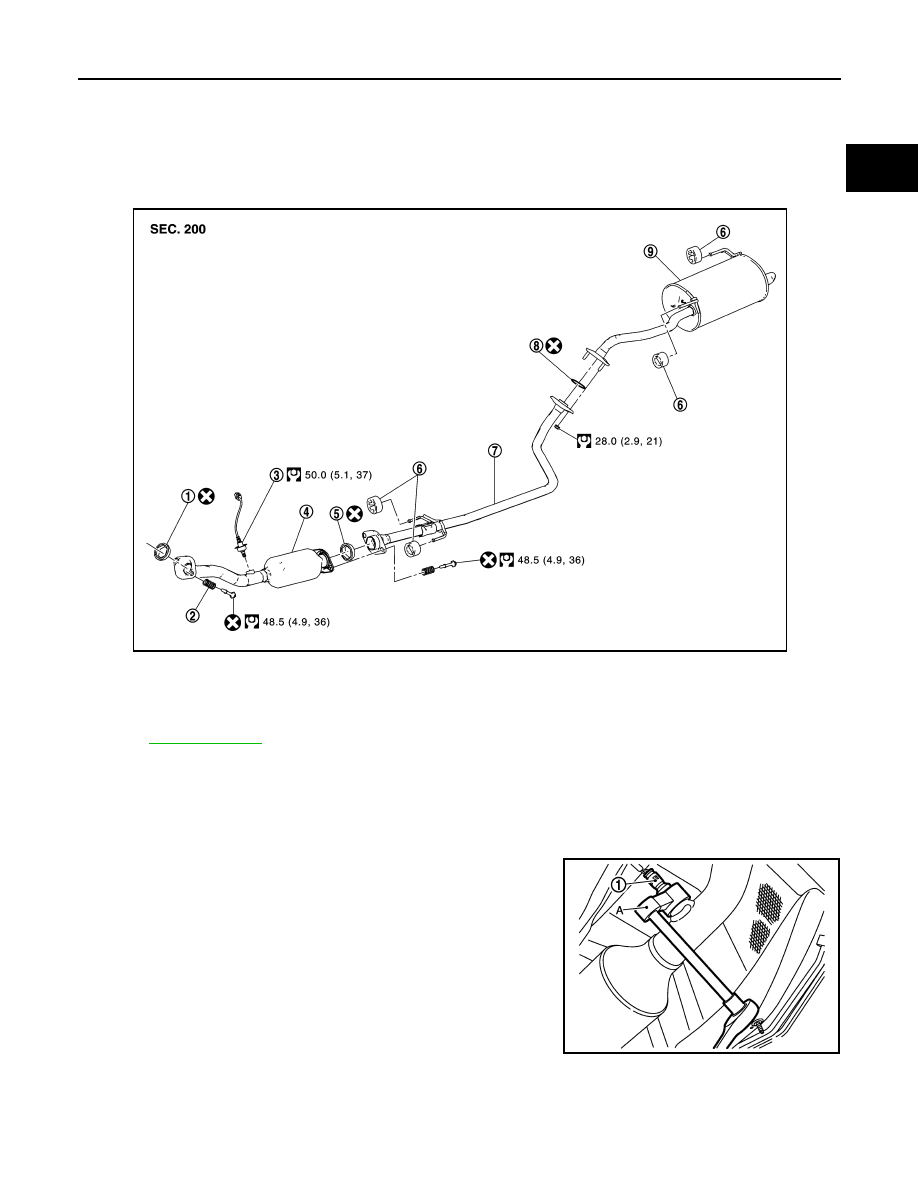
Exploded View
INFOID:0000000005988498
Removal and Installation
INFOID:0000000005988499
REMOVAL
• Disconnect each joint and mounting.
• Remove heated oxygen sensor 2 with following procedure:
- Using heated oxygen sensor wrench [SST: KV10114400] (A),
removal heated oxygen sensor 2 (1).
CAUTION:
Be careful not to damage heated oxygen sensor 2.
INSTALLATION
Note the following, and install in the reverse order of removal.
CAUTION:
• Always replace seal bearings with new ones when reassembling.
1.
Seal bearing
2.
Spring
3.
Heated oxygen sensor 2
4.
Exhaust front tube
5.
Seal bearing
6.
Mounting bracket
7.
Center muffler
8.
Ring gasket
9.
Main muffler
JPBIA3372GB
2
: Exhaust front tube
JPBIA3468ZZ