Nissan March K13. Manual - part 256


  Index      Nissan     Nissan March K13 - Service and Repair Manual)


Search            


Content   ..  254  255  256  257   ..


Nissan March K13. Manual - part 256


FUEL PUMP

EC-485

< DTC/CIRCUIT DIAGNOSIS >

[HR12DE (TYPE 2)]

C

D

E

F

G

H

I

J

K

L

M

A

EC

N

P

O

FUEL PUMP

Component Function Check

INFOID:0000000006046395

1.

CHECK FUEL PUMP FUNCTION

1.

Turn ignition switch ON.

2.

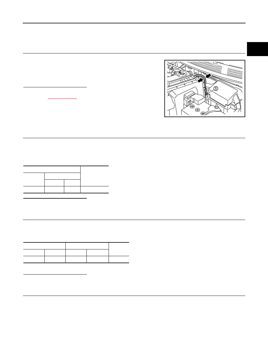
Pinch fuel feed hose (1) with two fingers.

Is the inspection result normal?

YES

>> INSPECTION END

NO

>>

XX-XX, "*****"

.

Diagnosis Procedure

INFOID:0000000006037615

1.

CHECK FUEL PUMP POWER SUPPLY CIRCUIT-I

1.

Turn ignition switch OFF.

2.

Disconnect ECM harness connector.

3.

Turn ignition switch ON.

4.

Check the voltage between ECM harness connector and ground.

Is the inspection result normal?

YES

>> GO TO 4.

NO

>> GO TO 2.

2.

CHECK FUEL PUMP POWER SUPPLY CIRCUIT-II

1.

Turn ignition switch OFF.

2.

Disconnect IPDM E/R harness connector.

3.

Check the continuity between IPDM E/R harness connector and ECM harness connector.

4.

Also check harness for short to ground and short to power.

Is the inspection result normal?

YES

>> GO TO 10.

NO

>> GO TO 3.

3.

DETECT MALFUNCTIONING PART

Check the following.
• Harness or connectors E6, F1
• IPDM E/R connector E12
• Harness for open or short to ground and short power

>> Repair open circuit or short to ground or short to power in harness or connectors.

Fuel pressure pulsation should be felt on the fuel feed 
hose for 1 second after ignition switch is turned ON.

JSBIA0377ZZ

ECM

Voltage

Connector

Terminal

+

F7

23

108

Battery voltage

ECM

IPDM E/R

Continuity

Connector

Terminal

Connector

Terminal

F7

23

E12

31

Existed

EC-486

< DTC/CIRCUIT DIAGNOSIS >

[HR12DE (TYPE 2)]

FUEL PUMP

4.

CHECK FUEL PUMP POWER SUPPLY CIRCUIT-III

1.

Turn ignition switch OFF.

2.

Reconnect all harness connectors disconnected.

3.

Disconnect “fuel level sensor unit and fuel pump” harness connector.

4.

Turn ignition switch ON.

5.

Check voltage between “fuel level sensor unit and fuel pump” harness connector and ground. 

Is the inspection result normal?

YES

>> GO TO 8.

NO

>> GO TO 5.

5.

CHECK 15 A FUSE

1.

Turn ignition switch OFF.

2.

Disconnect 15 A fuse (No. 60) from IPDM E/R.

3.

Check 15 A fuse.

Is the inspection result normal?

YES

>> GO TO 6.

NO

>> Replace fuse.

6.

CHECK FUEL PUMP POWER SUPPLY CIRCUIT-IV

1.

Disconnect IPDM E/R harness connector.

2.

Check the continuity between IPDM E/R harness connector and “fuel level sensor unit and fuel pump”
harness connector.

3.

Also check harness for short to ground and short to power.

Is the inspection result normal?

YES

>> GO TO 10.

NO

>> GO TO 7.

7.

DETECT MALFUNCTIONING PART

Check the following.
• Harness connectors E105, M77
• Harness connectors B4, M15
• Harness for open or short between IPDM E/R and “fuel level sensor unit and fuel pump” 

>> Repair open circuit or short to ground or short to power in harness or connectors.

8.

CHECK FUEL PUMP GROUND CIRCUIT

1.

Check the continuity between “fuel level sensor unit and fuel pump” and ground. 

2.

Also check harness for short to power. 

Fuel level sensor unit 

and fuel pump

Ground

Voltage

Connector

Terminal

B40

4

Ground

Battery voltage should for exist 1 second af-
ter ignition switch is turn ON.

IPDM E/R

Fuel level sensor unit and 

fuel pump

Continuity

Connector

Terminal

Connector

Terminal

E14

55

B40

4

Existed

Fuel level sensor unit 

and fuel pump

Ground

Continuity

Connector

Terminal

B40

2

Ground

Existed

FUEL PUMP

EC-487

< DTC/CIRCUIT DIAGNOSIS >

[HR12DE (TYPE 2)]

C

D

E

F

G

H

I

J

K

L

M

A

EC

N

P

O

Is the inspection result normal?

YES

>> GO TO 9.

NO

>> Repair open circuit or short to power in harness or connectors.

9.

CHECK FUEL PUMP

Refer to 

XX-XX, "*****"

.

Is the inspection result normal?

YES

>> GO TO 10.

NO

>> Replace “fuel level sensor unit and fuel pump”.

10.

CHECK INTERMITTENT INCIDENT

Refer to 

XX-XX, "*****"

.

Is the inspection result normal?

YES

>> Replace IPDM E/R.

NO

>> Repair or replace harness or connectors.

Component Inspection (Fuel pump)

INFOID:0000000006066590

1.

CHECK FUEL PUMP

1.

Turn ignition switch OFF.

2.

Disconnect “fuel level sensor unit and fuel pump (main)” harness connector.

3.

Check resistance between “fuel level sensor unit and fuel pump (main)” terminals as follows.

Is the inspection result normal?

YES

>> INSPECTION END

NO

>> Replace “fuel level sensor unit and fuel pump (main)”

Terminals

Resistance

1 and 3

0.2 - 5.0 

 [at 25

°

C (77

°

F)]

EC-488

< DTC/CIRCUIT DIAGNOSIS >

[HR12DE (TYPE 2)]

HO2S1

HO2S1

Component Function Check

INFOID:0000000005886633

1.

CHECK HEATED OXYGEN SENSOR 1 FUNCTION

With CONSULT-III

1.

Start engine and warm it up to normal operating temperature.

2.

Select “HO2S1 MNITOR (B1)” in ”DATA MONITOR” mode with CONSULT-III.

3.

Keep the engine speed at 2,000 rpm under no load, and make
sure that the monitors fluctuates between LEAN and RICH more
than five times in 10 seconds.

 Without CONSULT-III

1.

Start engine and warm it up to normal operating temperature.

2.

Stop engine and wait at least 10 seconds.

3.

Set ECM in Diagnostic test mode - II (Heated oxygen sensor 1 monitor). Refer to 

EC-346, "Diagnosis

Description"

.

4.

Keep the engine speed at 2,000 rpm under no load, and make
sure that the MIL comes ON more than five times in 10 seconds.

Is the inspection result normal?

YES

>> INSPECTION END

NO

>> Go to 

EC-488, "Diagnosis Procedure"

.

Diagnosis Procedure

INFOID:0000000005886634

1.

CHECK GROUND CONNECTION

1.

Turn ignition switch OFF.

2.

Check ground connection E38. Refer to Ground Inspection in 

XX-XX, "*****"

.

Is the inspection result normal?

YES

>> GO TO 2.

NO

>> Repair or replace ground connection.

2.

RETIGHTEN HEATED OXYGEN SENSOR 1

Loosen and retighten the heated oxygen sensor 1. Refer to 

XX-XX, "*****"

.

>> GO TO 3.

3.

CHECK EXHAUST GAS LEAK

1.

Start engine and run it at idle.

1 times: RICH 

 LEAN 

 RICH

2 times: RICH 

 LEAN 

 RICH 

 LEAN 

 RICH

SEF217YA

SAT652J


Content   ..  254  255  256  257   ..