Nissan March K13. Manual - part 254
COOLING FAN
EC-477
< DTC/CIRCUIT DIAGNOSIS >
[HR12DE (TYPE 2)]
C
D
E
F
G
H
I
J
K
L
M
A
EC
N
P
O
>> Repair open circuit or short to ground or short to power in harness or connectors.
4.
CHECK COOLING FAN MOTOR
EC-477, "Component Inspection"
YES or NO
YES
>> GO TO 5.
NO
>> Replace cooling fan motor.
5.
CHECK INTERMITTENT INCIDENT
Perform
XX-XX, "*****"
.
YES or NO
YES
>> Replace IPDM E/R. Refer to
XX-XX, "*****"
(WITH I-KEY) or
XX-XX, "*****"
(WITHOUT I-KEY).
NO
>> Repair or replace harness or connector.
Component Inspection
INFOID:0000000006037458
1.
CHECK COOLING FAN MOTOR
1.
Turn ignition switch OFF.
2.
Disconnect cooling fan motor harness connector.
3.
Supply cooling fan motor terminals with battery voltage and check operation.
Is the inspection result normal?
YES
>> INSPECTION END
NO
>> Replace cooling fan motor.
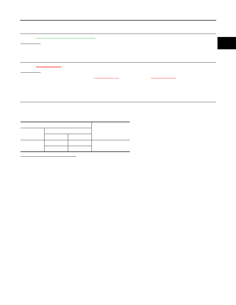
Cooling fan motor
Operation
Connector
terminals
(+)
(
−
)
E62
1
4
Cooling fan operates.
2
3