Nissan March K13. Manual - part 237


  Index      Nissan     Nissan March K13 - Service and Repair Manual)


Search            


Content   ..  235  236  237  238   ..


Nissan March K13. Manual - part 237


P0132 HO2S1

EC-409

< DTC/CIRCUIT DIAGNOSIS >

[HR12DE (TYPE 2)]

C

D

E

F

G

H

I

J

K

L

M

A

EC

N

P

O

P0132 HO2S1

DTC Logic

INFOID:0000000005886524
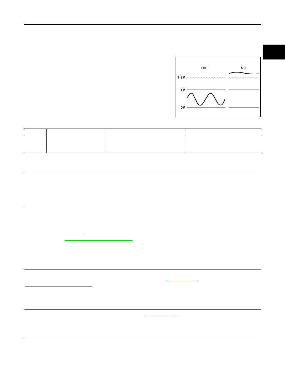
DTC DETECTION LOGIC

To judge the malfunction, the diagnosis checks that the heated oxy-
gen sensor 1 is not inordinately high.

DTC CONFIRMATION PROCEDURE

1.

PRECONDITIONING

If DTC Confirmation Procedure has been previously conducted, always turn ignition switch OFF and wait at
least 10 seconds before conducting the next test.

>> GO TO 2.

2.

PERFORM DTC CONFIRMATION PROCEDURE

1.

Start engine and warm it up to normal operating temperature.

2.

Turn ignition switch OFF and wait at least 10 seconds.

3.

Restart engine and let it idle for 2 minutes.

4.

Check 1st trip DTC.

Is 1st trip DTC is detected?

YES

>> Go to 

EC-409, "Diagnosis Procedure"

.

NO

>> INSPECTION END

Diagnosis Procedure

INFOID:0000000005886525

1.

CHECK GROUND CONNECTION

1.

Turn ignition switch OFF.

2.

Check ground connection E38. Refer to Ground Inspection in 

XX-XX, "*****"

.

Is the inspection result normal?

YES

>> GO TO 2.

NO

>> Repair or replace ground connection.

2.

RETIGHTEN HEATED OXYGEN SENSOR 1

Loosen and retighten heated oxygen sensor 1. Refer to 

XX-XX, "*****"

.

>> GO TO 3.

3.

CHECK HO2S1 GROUND CIRCUIT FOR OPEN AND SHORT

1.

Disconnect heated oxygen sensor 1 (HO2S1) harness connector.

2.

Disconnect ECM harness connector.

PBIB1848E

DTC No.

Trouble diagnosis name

DTC detecting condition

Possible Cause

P0132

Heated oxygen sensor 1 circuit 
high voltage

An excessively high voltage from the sensor 
is sent to ECM.

• Harness or connectors

(The sensor circuit is open or shorted.)

• Heated oxygen sensor 1

EC-410

< DTC/CIRCUIT DIAGNOSIS >

[HR12DE (TYPE 2)]

P0132 HO2S1

3.

Check harness continuity between HO2S1 harness connector and ECM harness connector.

4.

Also check harness for short to ground and short to power.

Is the inspection result normal?

YES

>> GO TO 4.

NO

>> Repair open circuit or short to ground or short to power in harness or connectors.

4.

CHECK HO2S1 INPUT SIGNAL CIRCUIT FOR OPEN AND SHORT

1.

Check harness continuity between HO2S1 harness connector and ECM harness connector.

2.

Check harness continuity between HO2S1 harness connector or ECM harness connector and ground.

3.

Also check harness for short to power.

Is the inspection result normal?

YES

>> GO TO 5.

NO

>> Repair open circuit or short to ground or short to power in harness or connectors.

5.

CHECK HO2S1 CONNECTOR FOR WATER

Check heated oxygen sensor 1 connector for water.

Is the inspection result normal?

YES

>> GO TO 6.

NO

>> Repair or replace harness or connectors.

6.

CHECK HEATED OXYGEN SENSOR 1

Refer to 

EC-410, "Component Inspection"

.

Is the inspection result normal?

YES

>> GO TO 7.

NO

>> Replace heated oxygen sensor 1.

7.

CHECK INTERMITTENT INCIDENT

Refer to 

XX-XX, "*****"

.

>> INSPECTION END

Component Inspection

INFOID:0000000005886526

1.

INSPECTION START

Do you have CONSULT-III?

Do you have CONSULT-III?

YES

>> GO TO 2.

NO

>> GO TO 3.

2.

CHECK HEATED OXYGEN SENSOR 1

 With CONSULT-III

HO2S1

ECM

Continuity

Connector

Terminal

Connector

Terminal

F46

1

F8

56

existed

HO2S1

ECM

Continuity

Connector

Terminal

Connector

Terminal

F46

4

F8

49

existed

HO2S1

ECM

Ground

Continuity

Connector

Terminal

Connector

Terminal

F46

4

F8

49

Ground

Not existed

P0132 HO2S1

EC-411

< DTC/CIRCUIT DIAGNOSIS >

[HR12DE (TYPE 2)]

C

D

E

F

G

H

I

J

K

L

M

A

EC

N

P

O

1.

Start engine and warm it up to normal operating temperature.

2.

Set “POST TRIGGER” to 100% in “DATA MONITOR” mode with CONSULT-III. 

3.

Select “HO2S1 (B1)” and “HO2S1 MNTR (B1)”.

4.

Hold engine speed at 2,000 rpm under no load during the following steps.

5.

Touch “RECORD” on CONSULT-III screen.

6.

Check the following.

-

“HO2S1 MNTR (B1)” in “DATA MONITOR” mode changes from
“RICH” to “LEAN” to “RICH” more than 5 times in 10 seconds.

5 times (cycles) are counted as shown in the figure.

-

“HO2S1 (B1)” voltage goes above 0.6 V at least once.

-

“HO2S1 (B1)” voltage goes below 0.3 V at least once.

-

“HO2S1 (B1)” voltage never exceeds 1.0 V.

Is the inspection result normal?

YES

>> INSPECTION END

NO

>> GO TO 4.

3.

CHECK HEATED OXYGEN SENSOR 1

 Without CONSULT-III

1.

Start engine and warm it up to normal operating temperature.

2.

Check the voltage between ECM harness connector and ground under the following condition.

Is the inspection result normal?

YES

>> INSPECTION END

NO

>> GO TO 4.

4.

REPLACE HEATED OXYGEN SENSOR 1

Replace heated oxygen sensor 1.

CAUTION:

• Discard any heated oxygen sensor which has been dropped from a height of more than 0.5 m (19.7

in) onto a hard surface such as a concrete floor; use a new one.

SEF217YA

JMBIA0352ZZ

ECM

Condition

Voltage

Connector

Terminal

+

F8

49

(HO2S1 

signal)

56

Engine speed held at 2,000 
rpm constant under no load.

• The voltage fluctuates between 0 to 0.3 V and 0.6 to 1.0 V 

more than 5 times within 10 seconds.

• The maximum voltage is over 0.6 V at least 1 time.
• The minimum voltage is below 0.3 V at least 1 time.
• The voltage never exceeds 1.0 V.
1 time: 0 - 0.3 V 

 0.6 - 1.0 V 

 0 - 0.3 V

2 times: 0 - 0.3 V 

 0.6 - 1.0 V 

 0 - 0.3 V 

 0.6 - 1.0 V 


0 - 0.3 V

EC-412

< DTC/CIRCUIT DIAGNOSIS >

[HR12DE (TYPE 2)]

P0132 HO2S1

• Before installing new heated oxygen sensor, clean exhaust system threads using Oxygen Sensor

Thread Cleaner (commercial service tool) and approved Anti-seize Lubricant (commercial service
tool).

>> INSPECTION END


Content   ..  235  236  237  238   ..