Nissan March K13. Manual - part 172
P0130 A/F SENSOR 1
EC-149
< DTC/CIRCUIT DIAGNOSIS >
[HR12DE (TYPE 1)]
C
D
E
F
G
H
I
J
K
L
M
A
EC
N
P
O
Check harness for open or short between A/F sensor 1 and fuse.
>> Repair or replace harness or connectors.
3.
CHECK A/F SENSOR 1 INPUT SIGNAL CIRCUIT FOR OPEN AND SHORT
1.
Turn ignition switch OFF.
2.
Disconnect ECM harness connector.
3.
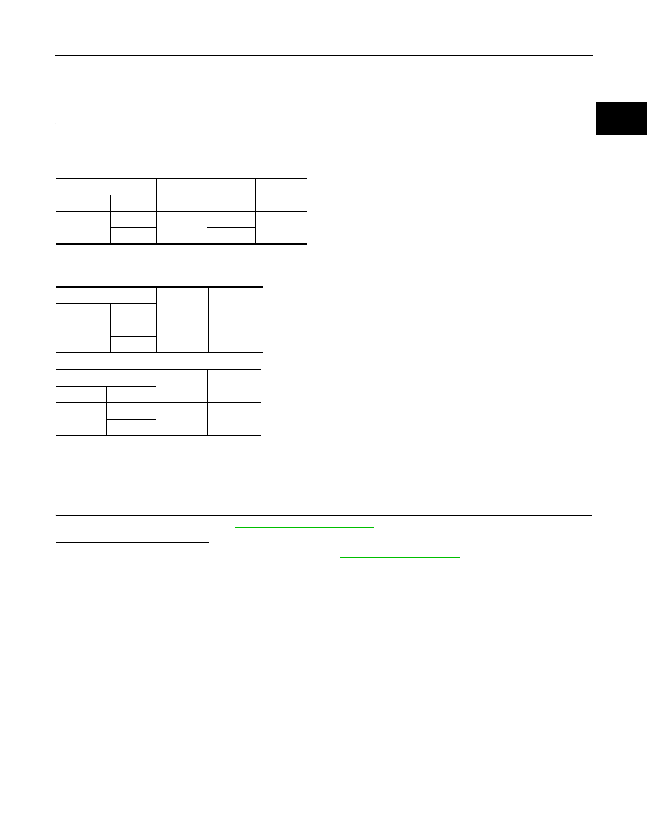
Check the continuity between A/F sensor 1 harness connector and ECM harness connector.
4.
Check the continuity between A/F sensor 1 harness connector and ground or ECM harness connector
and ground.
5.
Also check harness for short to power.
Is the inspection result normal?
YES
>> GO TO 4.
NO
>> Repair open circuit, short to ground or short to power in harness or connectors.
4.
CHECK INTERMITTENT INCIDENT
Check intermittent incident. Refer to
GI-33, "Intermittent Incident"
.
Is the inspection result normal?
YES
>> Replace air fuel ratio (A/F) sensor 1. Refer to
NO
>> Repair or replace.
A/F sensor 1
ECM
Continuity
Connector
Terminal
Connector
Terminal
F50
1
F16
49
Existed
2
53
A/F sensor 1
Ground
Continuity
Connector
Terminal
F50
1
Ground
Not existed
2
ECM
Ground
Continuity
Connector
Terminal
F16
49
Ground
Not existed
53