Nissan March K13. Manual - part 144


  Index      Nissan     Nissan March K13 - Service and Repair Manual)


Search            


Content   ..  142  143  144  145   ..


Nissan March K13. Manual - part 144


SYSTEM

EC-37

< SYSTEM DESCRIPTION >

[HR12DE (TYPE 1)]

C

D

E

F

G

H

I

J

K

L

M

A

EC

N

P

O

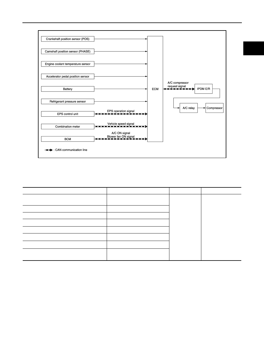
AIR CONDITIONING CUT CONTROL : System Diagram

INFOID:0000000005995404

AIR CONDITIONING CUT CONTROL : System Description

INFOID:0000000005995405

INPUT/OUTPUT SIGNAL CHART

*1: ECM determines the start signal status by the signals of engine speed and battery voltage.
*2: This signal is sent to the ECM through CAN communication line.

SYSTEM DESCRIPTION

This system improves engine operation when the air conditioner is used.
Under the following conditions, the air conditioner is turned off.
• When the accelerator pedal is fully depressed.
• When cranking the engine.
• At high engine speeds.
• When the engine coolant temperature becomes excessively high.
• When operating power steering during low engine speed or low vehicle speed.
• When engine speed is excessively low.
• When refrigerant pressure is excessively low or high.

JSBIA0320GB

Sensor

Input signal to ECM

ECM function

Actuator

Crankshaft position sensor (POS)
Camshaft position sensor (PHASE)

Engine speed

*1

A/C compressor 
repuest signal

IPDM E/R

Air conditioner relay

Compressor

Engine coolant temperature sensor

Engine coolant temperature

Accelerator pedal position sensor

Accelerator pedal position

Battery

Battery voltage

*1

Refrigerant pressure sensor

Refrigerant pressure

EPS control unit

EPS operation signal

*2

Combination meter

Vehicle speed signal

*2

BCM

A/C ON signal

*2

Blower fan ON signal

EC-38

< SYSTEM DESCRIPTION >

[HR12DE (TYPE 1)]

SYSTEM

CAN COMMUNICATION

CAN COMMUNICATION : System Description

INFOID:0000000005995406

CAN (Controller Area Network) is a serial communication line for real time application. It is an on-vehicle mul-
tiplex communication line with high data communication speed and excellent error detection ability. Many elec-
tronic control units are equipped onto a vehicle, and each control unit shares information and links with other
control units during operation (not independent). In CAN communication, control units are connected with 2
communication lines (CAN H line, CAN L line) allowing a high rate of information transmission with less wiring.
Each control unit transmits/receives data but selectively reads required data only.
Refer to 

LAN-23, "CAN COMMUNICATION SYSTEM : CAN Communication Signal Chart"

, about CAN com-

munication for detail.

COOLING FAN CONTROL

COOLING FAN CONTROL : System Diagram

INFOID:0000000005995407

COOLING FAN CONTROL : System Description

INFOID:0000000005995408

INPUT/OUTPUT SIGNAL CHART

*1: ECM determines the start signal status by the signals of engine speed and battery voltage.
*2: This signal is sent to ECM through CAN communication line.

SYSTEM DESCRIPTION

ECM controls cooling fan speed corresponding to vehicle speed, engine coolant temperature, refrigerant pres-
sure, air conditioner ON signal. Then control system has 2-step control [HIGH/OFF].

JSBIA0321GB

Sensor

Input signal to ECM

ECM function

Actuator

Crankshaft position sensor (POS)
Camshaft position sensor (PHASE)

Engine speed

*1

Cooling fan 
speed request 
signal

IPDM E/R

Cooling fan relay

Cooling fan motor

Engine coolant temperature sensor

Engine coolant temperature

Refrigerant pressure sensor

Refrigerant pressure

Battery

Battery voltage

*1

Combination meter

Vehicle speed signal

*2

BCM

A/C ON signal

*2

Blower fan ON signal

SYSTEM

EC-39

< SYSTEM DESCRIPTION >

[HR12DE (TYPE 1)]

C

D

E

F

G

H

I

J

K

L

M

A

EC

N

P

O

Cooling Fan Operation

Cooling Fan Relay Operation

The ECM controls cooling fan relays through CAN communication line.

EGR SYSTEM

EGR SYSTEM : System Diagram

INFOID:0000000005995409

JSBIA0415GB

Cooling fan speed

Cooling fan relay

Stop (OFF)

OFF

High (HI)

ON

JSBIA0324GB

EC-40

< SYSTEM DESCRIPTION >

[HR12DE (TYPE 1)]

SYSTEM

EGR SYSTEM : System Description

INFOID:0000000005995410

INPUT/OUTPUT SIGNAL CHART

*1: ECM determines the start signal status by the signals of engine speed and battery voltage.
*2: This signal is sent to the ECM through CAN communication line.

SYSTEM DESCRIPTION

This system controls the volume of EGR flowing from the exhaust manifold to the intake manifold. The EGR
volume control valve adjusts EGR volume by opening and closing the EGR passage. The step motor built in
the EGR volume control valve activates the valve, according to a signal transmitted from ECM. ECM deter-
mines a valve angle, according to driving conditions, such as an engine speed, load, combustion state and
precisely controls EGR volume. EGR is deactivated under the following conditions to enhance drivability:
• Engine starting
• Engine at idle
• Low engine coolant temperature
• high engine coolant temperature
• High engine speed
• Low intake air temperature
• Low battery voltage

EVAPORATIVE EMISSION SYSTEM

Sensor

Input signal to ECM

ECM function

Actuator

Crankshaft position sensor (POS)

Engine speed

*1

Piston position

EGR volume 
control

EGR volume control valve

Camshaft position sensor (PHASE)

Mass air flow sensor

Amount of intake air

Intake air temperature sensor

Intake air temperature

Engine coolant temperature sensor

Engine coolant temperature

Throttle position sensor

Throttle position

Accelerator pedal position sensor

Accelerator pedal position

Park/neutral position (PNP) switch

PNP signal

Battery

Battery voltage

*1

BCM

A/C ON signal

*2

Blower fan ON signal

*2

Combination meter

Vehicle speed signal

*2

IPDM E/R

High beam status signal

*2

Low beam status signal

*2

Rear window deffoger cotrol signal

*2

1.

EGR volume control valve

2.

EGR temperature sensor

3.

Electric throttle control actuator

PBIA9610J


Content   ..  142  143  144  145   ..