Nissan March K13. Manual - part 67


  Index      Nissan     Nissan March K13 - Service and Repair Manual)


Search            


Content   ..  65  66  67  68   ..


Nissan March K13. Manual - part 67


DEF-6

< SYSTEM DESCRIPTION >

SYSTEM

SYSTEM

REAR WINDOW DEFOGGER

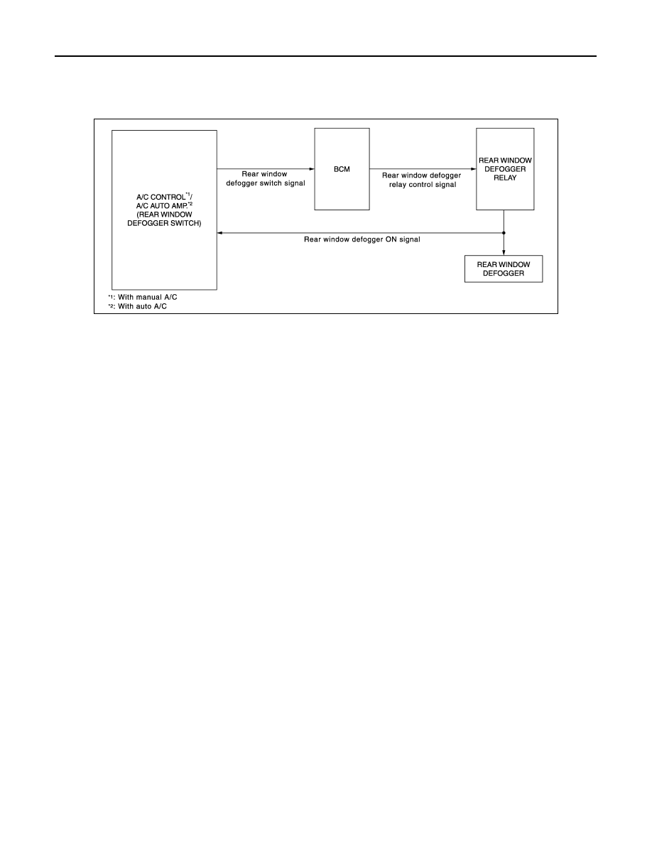
REAR WINDOW DEFOGGER : System Diagram

INFOID:0000000006067606

REAR WINDOW DEFOGGER : System Description

INFOID:0000000006067607

OPERATION DESCRIPTION

• Turn rear window defogger switch ON when the ignition switch is turned ON. Then A/C auto amp. (with auto

A/C) or A/C control (with manual A/C) transmits rear window defogger switch signal to BCM.

• BCM turns rear window defogger relay ON when rear window defogger switch signal is received.
• Rear window defogger are supplied with power and operate when rear window defogger relay turns ON.
• When rear window defogger is activated, indicator lamp on rear window defogger switch turns ON.

TIMER FUNCTION

• BCM turns rear window defogger relay ON for approximately 15 minutes when rear window defogger switch

is turned ON while ignition switch is ON. It makes rear window defogger operate.

• The timer is cancelled if the rear window defogger switch is pressed again during timer operation. BCM

stops the output of rear window defogger switch signal. The same action occurs during timer operation if the
ignition switch is OFF.

JMLIA1019GB

DIAGNOSIS SYSTEM (BCM) (WITH INTELLIGENT KEY SYSTEM)

DEF-7

< SYSTEM DESCRIPTION >

C

D

E

F

G

H

I

J

K

M

A

B

DEF

N

O

P

DIAGNOSIS SYSTEM (BCM) (WITH INTELLIGENT KEY SYSTEM)

COMMON ITEM

COMMON ITEM : CONSULT-III Function (BCM - COMMON ITEM)

INFOID:0000000006067664

APPLICATION ITEM

CONSULT-III performs the following functions via CAN communication with BCM.

SYSTEM APPLICATION

BCM can perform the following functions for each system.
NOTE:
It can perform the diagnosis modes except the following for all sub system selection items.

×

: Applicable item

*: This item is displayed, but is not used.

FREEZE FRAME DATA (FFD)

The BCM records the following vehicle condition at the time a particular DTC is detected, and displays on
CONSULT-III.

Diagnosis mode

Function Description

Work Support

Changes the setting for each system function.

Self Diagnostic Result

Displays the diagnosis results judged by BCM.

CAN Diag Support Monitor

Monitors the reception status of CAN communication viewed from BCM. Refer to CONSULT-III opera-
tion manual.

Data Monitor

The BCM input/output signals are displayed.

Active Test

The signals used to activate each device are forcibly supplied from BCM.

Ecu Identification

The BCM part number is displayed.

Configuration

• Read and save the vehicle specification.
• Write the vehicle specification when replacing BCM.

System

Sub system selection item

Diagnosis mode

Work Support

Data Monitor

Active Test

Door lock

DOOR LOCK

×

×

×

Rear window defogger

REAR DEFOGGER

×

×

Warning chime

BUZZER

×

×

Interior room lamp timer

INT LAMP

×

×

×

Exterior lamp

HEAD LAMP

×

×

×

Wiper and washer

WIPER

×

×

×

Turn signal and hazard warning lamps

FLASHER

×

×

×

Automatic air conditioner

AIR CONDITONER

×

×

• Intelligent Key system
• Engine start system

INTELLIGENT KEY

×

×

×

Combination switch

COMB SW

×

Body control system

BCM

×

NATS

IMMU

×

×

×

Interior room lamp battery saver

BATTERY SAVER

×

×

×

Back door

TRUNK

×

THEFT ALM*

×

×

×

RETAINED PWR*

×

Signal buffer system

SIGNAL BUFFER

×

×

DEF-8

< SYSTEM DESCRIPTION >

DIAGNOSIS SYSTEM (BCM) (WITH INTELLIGENT KEY SYSTEM)

REAR WINDOW DEFOGGER

REAR WINDOW DEFOGGER : CONSULT-III Function (BCM - REAR DEFOGGER)

INFOID:0000000006067609

Data monitor

ACTIVE TEST

CONSULT screen item

Indication/Unit

Description

Vehicle Speed

km/h

Vehicle speed of the moment a particular DTC is detected

Odo/Trip Meter

km

Total mileage (Odometer value) of the moment a particular DTC is detected

Vehicle Condition

SLEEP>LOCK

Power position status of 
the moment a particular 
DTC is detected

While turning BCM status from low power consumption mode to 
normal mode (Power supply position is “LOCK”)

SLEEP>OFF

While turning BCM status from low power consumption mode to 
normal mode (Power supply position is “OFF”.)

LOCK>ACC

While turning power supply position from “LOCK” to “ACC”

ACC>ON

While turning power supply position from “ACC” to “IGN”

RUN>ACC

While turning power supply position from “RUN” to “ACC” (Vehicle 
is stopping and selector lever is except P position.)

CRANK>RUN

While turning power supply position from “CRANKING” to “RUN” 
(From cranking up the engine to run it)

RUN>URGENT

While turning power supply position from “RUN“ to “ACC” (Emer-
gency stop operation)

ACC>OFF

While turning power supply position from “ACC” to “OFF”

OFF>LOCK

While turning power supply position from “OFF” to “LOCK”

OFF>ACC

While turning power supply position from “OFF” to “ACC”

ON>CRANK

While turning power supply position from “IGN” to “CRANKING”

OFF>SLEEP

While turning BCM status from normal mode (Power supply posi-
tion is “OFF”.) to low power consumption mode

LOCK>SLEEP

While turning BCM status from normal mode (Power supply posi-
tion is “LOCK”.) to low power consumption mode

LOCK

Power supply position is “LOCK” (Ignition switch OFF with steer-
ing is locked.)

OFF

Power supply position is “OFF” (Ignition switch OFF with steering 
is unlocked.)

ACC

Power supply position is “ACC” (Ignition switch ACC)

ON

Power supply position is “IGN” (Ignition switch ON with engine 
stopped)

ENGINE RUN

Power supply position is “RUN” (Ignition switch ON with engine 
running)

CRANKING

Power supply position is “CRANKING” (At engine cranking)

IGN Counter

0 - 39

The number of times that ignition switch is turned ON after DTC is detected
• The number is 0 when a malfunction is detected now.
• The number increases like 1 

 2 

 3...38 

 39 after returning to the normal condition 

whenever ignition switch OFF 

 ON.

• The number is fixed to 39 until the self-diagnosis results are erased if it is over 39.

Monitor Item

Description

REAR DEF SW

Displays “Press (ON)/other (OFF)” status determined with the rear window defogger switch.

PUSH SW

Indicates [ON/OFF] condition of push switch.

DIAGNOSIS SYSTEM (BCM) (WITH INTELLIGENT KEY SYSTEM)

DEF-9

< SYSTEM DESCRIPTION >

C

D

E

F

G

H

I

J

K

M

A

B

DEF

N

O

P

Test Item

Description

REAR DEFOGGER

Give a drive signal to the rear window defogger relay to activate it.


Content   ..  65  66  67  68   ..