Nissan March K13. Manual - part 57
CL-12
< REMOVAL AND INSTALLATION >
CLUTCH MASTER CYLINDER
CLUTCH MASTER CYLINDER
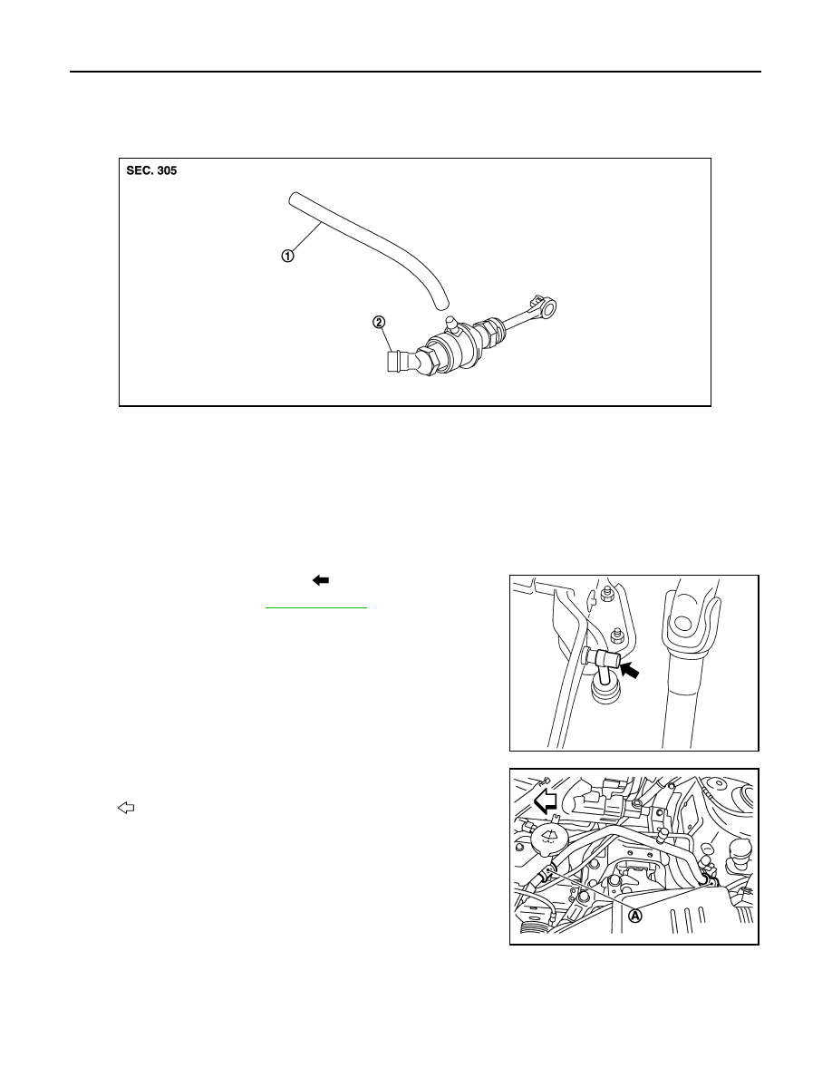
Exploded View
INFOID:0000000006056608
Removal and Installation
INFOID:0000000006056609
REMOVAL
CAUTION:
• Keep painted surface on the body or other parts free of clutch fluid. If it spills, wipe up immediately
and wash the affected area with water.
• Never disassemble clutch master cylinder.
1.
Remove master cylinder rod end (
) from clutch pedal.
2.
Drain clutch fluid. Refer to
.
3.
Remove reservoir hose from reservoir tank and master cylinder.
4.
Remove clips (A) for cooler pipe (low-pressure pipe).
1.
Reservoir hose
2.
Master cylinder
JPDIB0222ZZ
PCIB1491E
: Vehicle front
JPDIB0226ZZ