Nissan March K13. Manual - part 10


  Index      Nissan     Nissan March K13 - Service and Repair Manual)


Search            


Content   ..  8  9  10  11   ..


Nissan March K13. Manual - part 10


BCS

SYSTEM

BCS-13

< SYSTEM DESCRIPTION >

[WITH INTELLIGENT KEY SYSTEM]

C

D

E

F

G

H

I

J

K

L

B

A

O

P

N

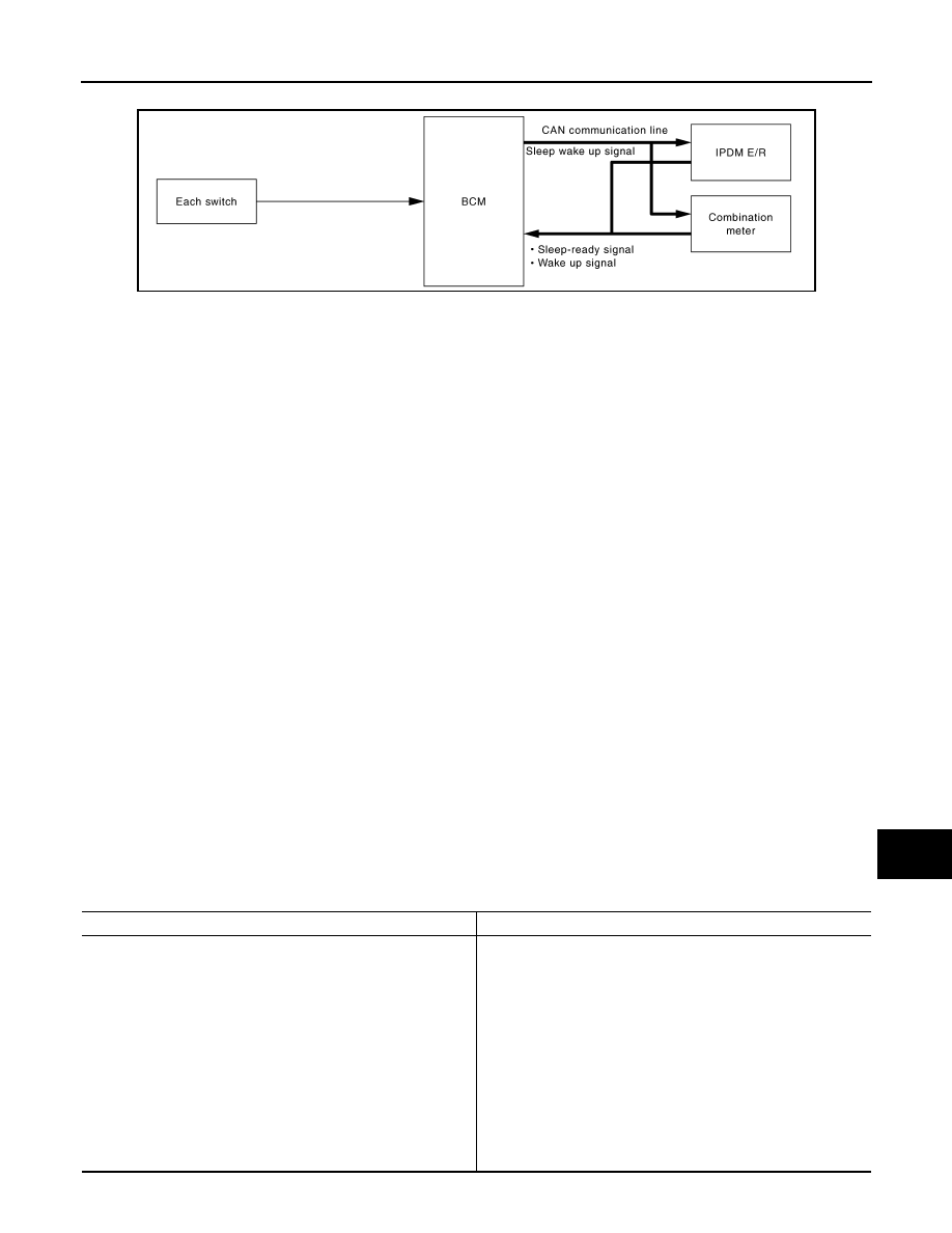
POWER CONSUMPTION CONTROL SYSTEM : System Diagram

INFOID:0000000006014821

POWER CONSUMPTION CONTROL SYSTEM : System Description

INFOID:0000000006014822

OUTLINE

• BCM incorporates a power saving control function that reduces the power consumption according to the

vehicle status. 

• BCM switches the status (control mode) by itself with the power saving control function. It performs the sleep

request to each unit (IPDM E/R and combination meter) that operates with the ignition switch OFF.

Normal mode (wake-up)

- CAN communication is normally performed with other units
- Each control with BCM is operating properly

CAN communication sleep mode (CAN sleep)

- CAN transmission is stopped
- Control with BCM only is operating

Low power consumption mode (BCM sleep)

- Low power consumption control is active
- CAN transmission is stopped

LOW POWER CONSUMPTION CONTROL WITH BCM

BCM reduces the power consumption with the following operation in the low power consumption mode.
• The reading interval of the each switches changes from 10 ms interval to 60 ms interval.

Sleep mode activation

• BCM receives the sleep-ready signal (ready) from IPDM E/R and combination meter via CAN communica-

tion.

• BCM transmits the sleep wake up signal (sleep) to each unit when all of the CAN sleep conditions are ful-

filled.

• Each unit stops the transmission of CAN communication with the sleep wake up signal. BCM is in CAN com-

munication sleep mode.

• BCM is in the low power consumption mode and perform the low power consumption control when all of the

BCM sleep conditions are fulfilled with CAN sleep condition.

Sleep condition

JPMIA0731GB

CAN sleep condition

BCM sleep condition

• Receiving the sleep-ready signal (ready) from all units
• Ignition switch: OFF
• Panic alarm: Not operation
• Warning chime: Not operation
• Intelligent Key system buzzer: Not operation
• Stop lamp switch: OFF
• Turn signal indicator lamp: Not operation
• Exterior lamp: OFF
• Door lock status: No change
• CONSULT-III communication status: Not communication
• Meter display signal: Non-transmission
• Door switch status: No change
• Rear window defogger: OFF
• Driver door lock status: No change

• Interior room lamp battery saver: Time out
• Nissan anti-theft system (NATS): Not operation
• Remote keyless entry receiver communication status: No com-

munication

• ACC/ON indicator lamp: Not operation

BCS-14

< SYSTEM DESCRIPTION >

[WITH INTELLIGENT KEY SYSTEM]

SYSTEM

Wake-up operation

• BCM transmits sleep wake up signal (wake up) to each unit when any condition listed below is established,

and then goes into normal mode from low power consumption mode.

• Each unit starts transmissions with CAN communication by receiving sleep wake up signals. Each unit trans-

mit wake up signals to BCM with CAN communication to convey the start of CAN communication.

Wake-up condition

Wake-up condition

• Receiving the sleep-ready signal (Not-ready) from any units
• Push-button ignition switch (push switch): OFF

 ON

• Hazard switch: ON
• HI BEAM switch: OFF 

 ON, ON 

 OFF

• PASSING switch: OFF 

 ON, ON 

 OFF

• HEADLAMP 1 switch: OFF 

 ON, ON 

 OFF

• HEADLAMP 2 switch: OFF 

 ON, ON 

 OFF

• TAIL LAMP switch: OFF 

 ON

• FR FOG switch: OFF 

 ON, ON 

 OFF

• TURN RH: OFF 

 ON, ON 

 OFF

• TURN LH: OFF 

 ON, ON 

 OFF

• Driver door switch: OFF 

 ON, ON 

 OFF

• Passenger door switch: OFF 

 ON, ON 

 OFF

• Rear RH door switch: OFF 

 ON, ON 

 OFF

• Rear LH door switch: OFF 

 ON, ON 

 OFF

• Back door switch: OFF 

 ON, ON 

 OFF

• Driver door request switch: OFF 

 ON

• Passenger door request switch: OFF 

 ON

• Back door request switch: OFF 

 ON

• Stop lamp switch: ON
• Door lock and unlock switch:

NEUTRAL 

 LOCK, NEUTRAL 

 UNLOCK

• Remote keyless entry receiver communication: Receiving
• Front door lock assembly (driver side) (unlock sensor):

OFF 

 ON, ON 

 OFF

BCS

DIAGNOSIS SYSTEM (BCM)

BCS-15

< SYSTEM DESCRIPTION >

[WITH INTELLIGENT KEY SYSTEM]

C

D

E

F

G

H

I

J

K

L

B

A

O

P

N

DIAGNOSIS SYSTEM (BCM)

COMMON ITEM

COMMON ITEM : CONSULT-III Function (BCM - COMMON ITEM)

INFOID:0000000006014823

APPLICATION ITEM

CONSULT-III performs the following functions via CAN communication with BCM.

SYSTEM APPLICATION

BCM can perform the following functions for each system.
NOTE:
It can perform the diagnosis modes except the following for all sub system selection items.

×

: Applicable item

*: This item is displayed, but is not used.

FREEZE FRAME DATA (FFD)

The BCM records the following vehicle condition at the time a particular DTC is detected, and displays on
CONSULT-III.

Diagnosis mode

Function Description

Work Support

Changes the setting for each system function.

Self Diagnostic Result

Displays the diagnosis results judged by BCM.

CAN Diag Support Monitor

Monitors the reception status of CAN communication viewed from BCM. Refer to CONSULT-III opera-
tion manual.

Data Monitor

The BCM input/output signals are displayed.

Active Test

The signals used to activate each device are forcibly supplied from BCM.

Ecu Identification

The BCM part number is displayed.

Configuration

• Read and save the vehicle specification.
• Write the vehicle specification when replacing BCM.

System

Sub system selection item

Diagnosis mode

Work Support

Data Monitor

Active Test

Door lock

DOOR LOCK

×

×

×

Rear window defogger

REAR DEFOGGER

×

×

Warning chime

BUZZER

×

×

Interior room lamp timer

INT LAMP

×

×

×

Exterior lamp

HEAD LAMP

×

×

×

Wiper and washer

WIPER

×

×

×

Turn signal and hazard warning lamps

FLASHER

×

×

×

Automatic air conditioner

AIR CONDITONER

×

×

• Intelligent Key system
• Engine start system

INTELLIGENT KEY

×

×

×

Combination switch

COMB SW

×

Body control system

BCM

×

NATS

IMMU

×

×

×

Interior room lamp battery saver

BATTERY SAVER

×

×

×

Back door

TRUNK

×

THEFT ALM*

×

×

×

RETAINED PWR*

×

Signal buffer system

SIGNAL BUFFER

×

×

BCS-16

< SYSTEM DESCRIPTION >

[WITH INTELLIGENT KEY SYSTEM]

DIAGNOSIS SYSTEM (BCM)

COMB SW

COMB SW : CONSULT-III Function (BCM - COMB SW)

INFOID:0000000006014834

DATA MONITOR

CONSULT screen item

Indication/Unit

Description

Vehicle Speed

km/h

Vehicle speed of the moment a particular DTC is detected

Odo/Trip Meter

km

Total mileage (Odometer value) of the moment a particular DTC is detected

Vehicle Condition

SLEEP>LOCK

Power position status of 
the moment a particular 
DTC is detected

While turning BCM status from low power consumption mode to 
normal mode (Power supply position is “LOCK”)

SLEEP>OFF

While turning BCM status from low power consumption mode to 
normal mode (Power supply position is “OFF”.)

LOCK>ACC

While turning power supply position from “LOCK” to “ACC”

ACC>ON

While turning power supply position from “ACC” to “IGN”

RUN>ACC

While turning power supply position from “RUN” to “ACC” (Vehicle 
is stopping and selector lever is except P position.)

CRANK>RUN

While turning power supply position from “CRANKING” to “RUN” 
(From cranking up the engine to run it)

RUN>URGENT

While turning power supply position from “RUN“ to “ACC” (Emer-
gency stop operation)

ACC>OFF

While turning power supply position from “ACC” to “OFF”

OFF>LOCK

While turning power supply position from “OFF” to “LOCK”

OFF>ACC

While turning power supply position from “OFF” to “ACC”

ON>CRANK

While turning power supply position from “IGN” to “CRANKING”

OFF>SLEEP

While turning BCM status from normal mode (Power supply posi-
tion is “OFF”.) to low power consumption mode

LOCK>SLEEP

While turning BCM status from normal mode (Power supply posi-
tion is “LOCK”.) to low power consumption mode

LOCK

Power supply position is “LOCK” (Ignition switch OFF with steer-
ing is locked.)

OFF

Power supply position is “OFF” (Ignition switch OFF with steering 
is unlocked.)

ACC

Power supply position is “ACC” (Ignition switch ACC)

ON

Power supply position is “IGN” (Ignition switch ON with engine 
stopped)

ENGINE RUN

Power supply position is “RUN” (Ignition switch ON with engine 
running)

CRANKING

Power supply position is “CRANKING” (At engine cranking)

IGN Counter

0 - 39

The number of times that ignition switch is turned ON after DTC is detected
• The number is 0 when a malfunction is detected now.
• The number increases like 1 

 2 

 3...38 

 39 after returning to the normal condition 

whenever ignition switch OFF 

 ON.

• The number is fixed to 39 until the self-diagnosis results are erased if it is over 39.

Monitor item [UNIT]

Description

FR WIPER HI
[Off/On]

Displays the status of the FR WIPER HI switch in combination switch judged by BCM with the combination 
switch reading function.

FR WIPER LOW
[Off/On]

Displays the status of the FR WIPER LOW switch in combination switch judged by BCM with the combination 
switch reading function.

FR WASHER SW
[Off/On]

Displays the status of the FR WASHER switch in combination switch judged by BCM with the combination 
switch reading function.


Content   ..  8  9  10  11   ..