Almera Tino V10 (2003 year). Manual - part 238
MEL145L
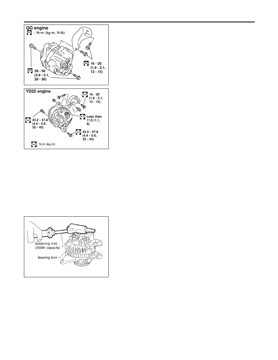
Removal and Installation
NLSC0013
REMOVAL (QG ENGINE)
NLSC0013S01
1.
Loosen drive belt idler pulley.
2.
Remove drive belt idler pulley (include tightening screw).
3.
Remove alternator harness.
4.
Remove alternator upper bolt and lower bolt.
5.
Remove alternator.
NEL645
REMOVAL (YD ENGINE)
NLSC0013S03
1.
Remove alternator harness.
2.
Loosen alternator upper nut and lower bolt.
3.
Loosen drive belt.
4.
Remove alternator bracket bolts (two).
5.
Remove alternator upper nut and lower bolt.
6.
Remove alternator.
INSTALLATION
NLSC0013S02
To install, reverse the removal procedure.
SEL032Z
Disassembly
NLSC0021
REAR COVER
NLSC0021S01
CAUTION:
Rear cover may be hard to remove because a ring is used to
lock outer race of rear bearing. To facilitate removal of rear
cover, heat just bearing box section with a 200W soldering
iron.
Do not use a heat gun, as it can damage diode assembly.
REAR BEARING
NLSC0021S02
CAUTION:
I
Do not reuse rear bearing after removal. Replace with a
new one.
I
Do not lubricate rear bearing outer race.
CHARGING SYSTEM
Removal and Installation
SC-28