Almera Tino V10 (2003 year). Manual - part 228
SMT695D
I
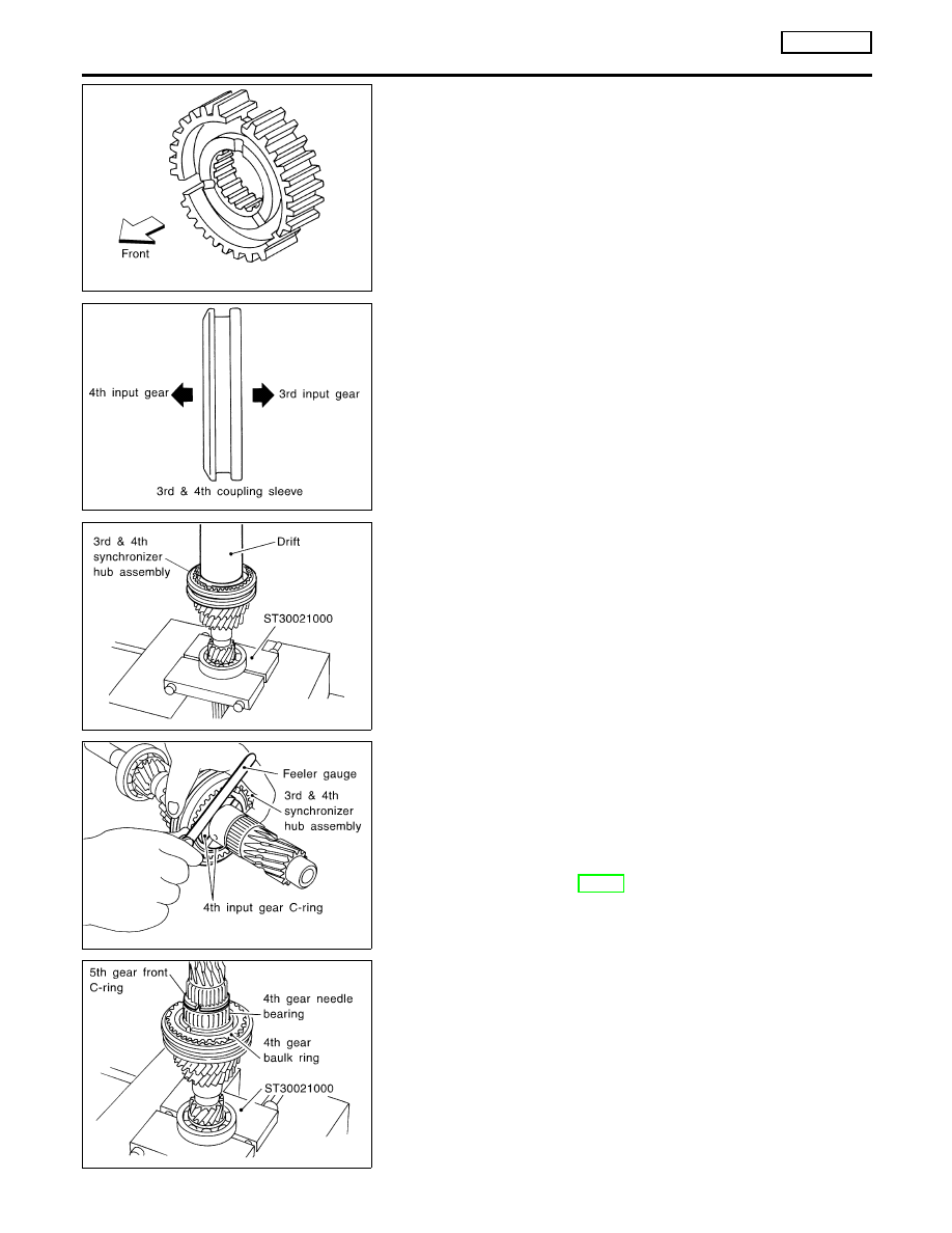
Install synchronizer hub with its three grooves facing the front
side (3rd input gear side).
SMT699D
I
Install 3rd & 4th coupling sleeve with its chamfered surface
facing the 4th input gear side.
SMT698DB
4.
Position bearing replacer to the front side of input shaft front
bearing.
I
Align grooves of shifting insert and 3rd gear baulk ring. Then,
press it onto 3rd & 4th synchronizer hub assembly using a drift.
5.
Install 4th gear C-ring onto input shaft.
SMT700DA
6.
Measure the end play of 3rd & 4th synchronizer hub, and
check if it is within allowable specification below.
End play:
0 - 0.06 mm (0 - 0.0024 in)
7.
If not within specification, adjust the end play by changing
thickness of 4th input gear C-ring.
4th input gear C-ring:
Refer to SDS, MT-91.
SMT701DB
8.
Install 4th gear needle bearing, 4th gear baulk ring, and 5th
gear front C-ring.
9.
Install 4th input gear.
REPAIR FOR COMPONENT PARTS
RS5F70A
Input Shaft and Gears (Cont’d)
MT-38