Almera Tino V10 (2003 year). Manual - part 226
Tool name
Description
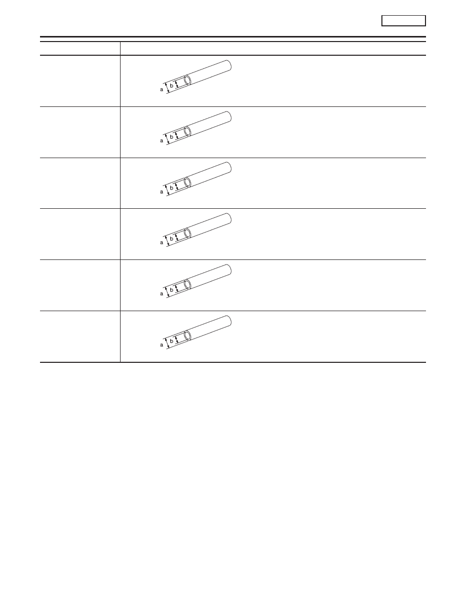
Drift
NT065
Removing input shaft rear bearing
Removing mainshaft rear bearing
a: 22 mm (0.87 in) dia.
b: 16 mm (0.63 in) dia.
Drift
NT065
Installing differential oil seal
a: 58 mm (2.28 in) dia.
b: 50 mm (1.97 in) dia.
Drift
NT065
Installing differential oil seal
a: 54 mm (2.13 in) dia.
b: 50 mm (1.97 in) dia.
Drift
NT065
Installing 2nd gear bush
a: 38 mm (1.50 in) dia.
b: 33 mm (1.30 in) dia.
Drift
NT065
Installing 3rd & 4th and 1st & 2nd synchronizer
hub
Installing mainshaft front bearing
a: 50 mm (1.97 in) dia.
b: 41 mm (1.61 in) dia.
Drift
NT065
Installing input shaft oil seal
Installing 5th input gear
a: 39 mm (1.54 in) dia.
b: 30 mm (1.18 in) dia.
PREPARATION
RS5F70A
Commercial Service Tools (Cont’d)
MT-6