Almera Tino V10 (2003 year). Manual - part 153
DTC P1274 FUEL PUMP
EC-1467
[YD (WITHOUT EURO-OBD)]
C
D
E
F
G
H
I
J
K
L
M
A
EC
DTC P1274 FUEL PUMP
PFP:16700
Description
EBS014ZV
To control the amount of the fuel inhalation of the fuel pump, a plunger is built into the fuel pump. When the
amount of the fuel inhalation of fuel increases, the fuel pump raises the fuel exhalation pressure. As a result,
the fuel injection pressure is raised. When the load of the engine increases, the ECM sends a signal to the fuel
pump to raise the injection pressure.
CONSULT-II Reference Value in Data Monitor Mode
EBS014ZW
Specification data are reference values.
ECM Terminals and Reference Value
EBS014ZX
Specification data are reference values and are measured between each terminal and ground.
Pulse signal is measured by CONSULT-II.
CAUTION:
Do not use ECM ground terminals when measuring input/output voltage. Doing so may result in dam-
age to the ECM's transistor. Use a ground other than ECM terminals, such as the ground.
MONITOR ITEM
CONDITION
SPECIFICATION
PUMP CURRENT
●
Engine: After warming up
●
Air conditioner switch: OFF
●
Shift lever: Neutral position
●
No-load
Idle
1,700 - 1,900 mA
2,000 rpm
1,600 - 1,800 mA
TERMI-
NAL
NO.
WIRE
COLOR
ITEM
CONDITION
DATA
(DC Voltage and Pulse Signal)
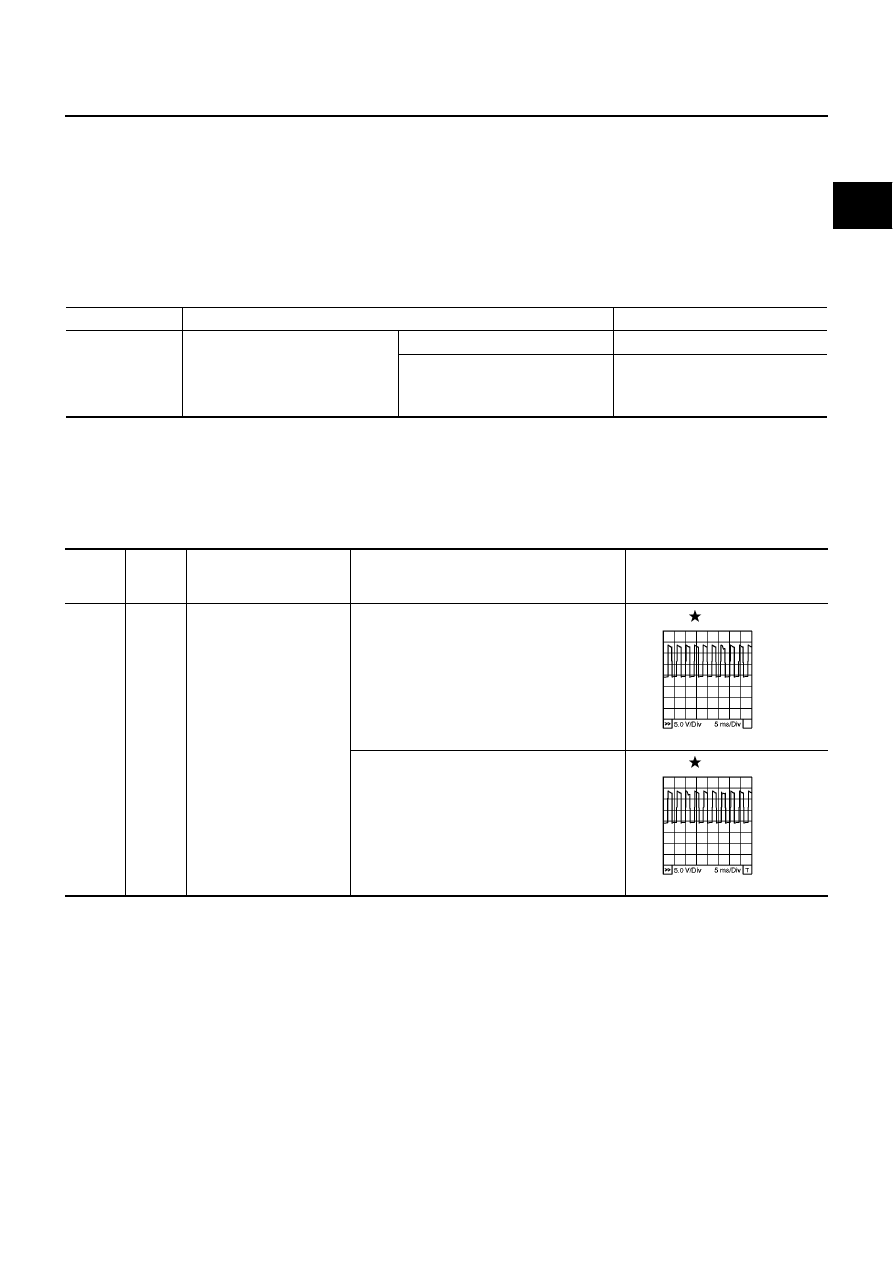
10
Y/L
Fuel pump power supply
[Engine is running]
●
Warm-up condition
●
Idle speed
0 - 12.5V
[Engine is running]
●
Warm-up condition
●
Engine speed is 2,000 rpm
0 - 12.5V
MBIB0885E
MBIB0886E