Almera Tino V10 (2003 year). Manual - part 93
DTC P1706 PNP SWITCH
EC-507
[QG (WITH EURO-OBD)]
C
D
E
F
G
H
I
J
K
L
M
A
EC
Specification data are reference values and are measured between each terminal and ground.
CAUTION:
Do not use ECM ground terminals when measuring input/output voltage. Doing so may result in dam-
age to the ECM's transistor. Use a ground other than ECM terminals, such as the ground.
Diagnostic Procedure
EBS00QSZ
1.
CHECK PNP SWITCH GROUND CIRCUIT FOR OPEN AND SHORT
1.
Turn ignition switch “OFF”.
2.
Disconnect PNP switch harness connector.
3.
Check harness continuity between PNP switch terminal 2 and
ground.
Refer to Wiring Diagram.
4.
Also check harness for short to power.
OK or NG
OK
>> GO TO 3.
NG
>> GO TO 2. (M/T models)
NG
>> Repair open circuit or short to power in harness or con-
nectors. (A/T models)
2.
DETECT MALFUNCTIONING PART
Check the following.
●
Harness connectors M71, F45
●
Harness for open or short between Park/Neutral position (PNP) switch and ground
>> Repair open circuit or short to power in harems or connectors
3.
CHECK PNP SWITCH INPUT SIGNAL CIRCUIT FOR OPEN AND SHORT
1.
Disconnect ECM harness connector.
2.
Check harness continuity between ECM terminal 102 and PNP switch terminal 1.
Refer to Wiring Diagram.
3.
Also check harness for short to ground and short to power.
OK or NG
OK
>> GO TO 3.
NG
>> GO TO 4.
TER-
MINAL
NO.
WIRE
COLOR
ITEM
CONDITION
DATA (DC Voltage)
102
P (A/T)
G/OR (M/T)
PNP switch
[Ignition switch “ON”]
●
Shift lever position is “P” or “N” (A/T models),
“Neutral” (M/T models).
Approximately 0V
[Ignition switch “ON”]
●
Except the above gear position
A/T models
BATTERY VOLTAGE
(11 - 14V)
M/T models
Approximately 5V
Continuity should exist.
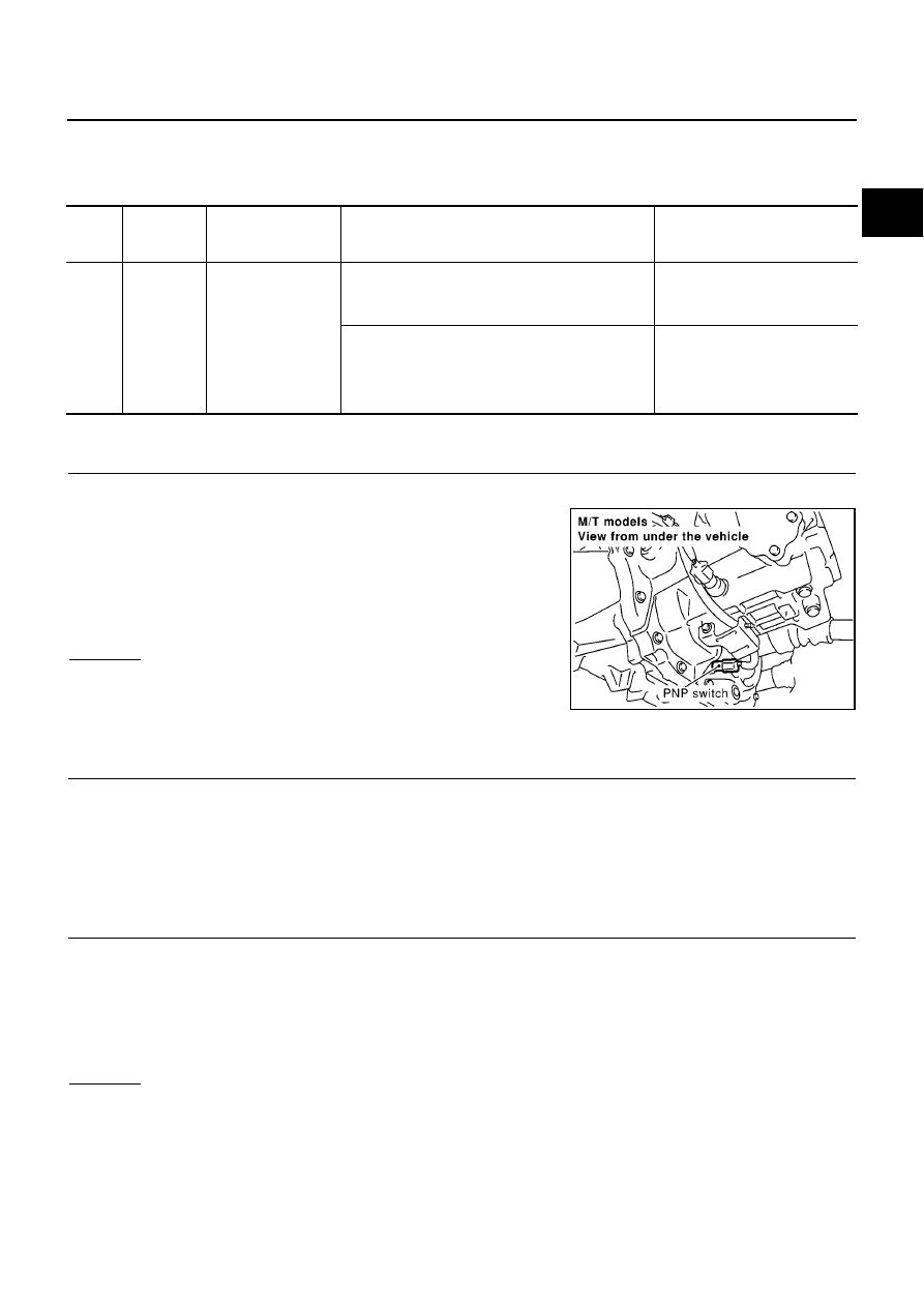
MBIB0110E
Continuity should exist.