Almera Tino V10 (2003 year). Manual - part 89
DTC P1146, P1166 HO2S2 (A/T MODELS)
EC-443
[QG (WITH EURO-OBD)]
C
D
E
F
G
H
I
J
K
L
M
A
EC
Procedure for COND2
1.
While driving, release accelerator pedal completed with “OD”
OFF from the above condition [step 9] until “INCOMPLETE” at
“COND2” on CONSULT-II screen has turned to “COMPLETED”
(It will take approximately 4 seconds.)
NOTE:
If “COMPLETE” already appears at “COND3” on CONSULT-
II screen before “Procedure for COND3” is conducted, it is
unnecessary to conduct step 1 in “Procedure for COND3”.
Procedure for COND3
1.
Stop vehicle and let it idle until “INCOMPLETE” of “COND3” on
CONSULT-II screen has turned to COMPLETED”. (It will take a
maximum of approximately 6 minutes.)
2.
Make sure that “OK” is displayed after touching “SELF-DIAG
RESULTS”.
If “NG” is displayed, refer to
EC-447, "Diagnostic Procedure"
.
If “CAN NOT BE DIAGNOSED” is displayed, perform the follow-
ing.
a.
Turn ignition switch “OFF” and leave the vehicle in a cool place
(soak the vehicle).
b.
Turn ignition switch “ON” and select “COOLANTEMP/S” in
“DATA MONITOR” mode with CONSULT-II
c.
Start engine and warm it up while monitoring “COOLANTEMP/S” indication on CONSULT-II.
d.
When “COOLANTEMP/S” indication reaches to 70
°
C (158
°
F), go to “Procedure for COND 1” step 3.
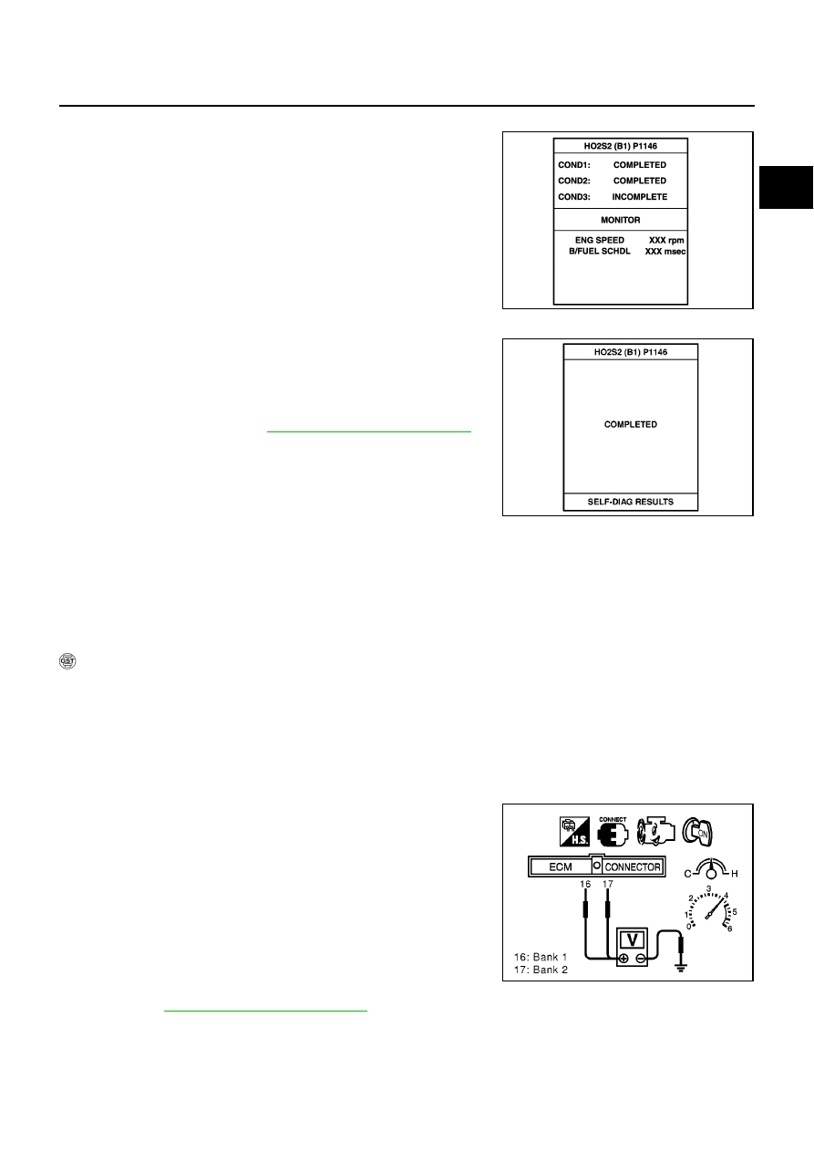
Overall Function Check
EBS00QQW
Use this procedure to check the overall function of the heated oxygen sensor 2 circuit. During this check, a
DTC might not be confirmed.
WITH GST
1.
Start engine and warm it up to the normal operating temperature.
2.
Turn ignition switch “OFF” and wait at least 10 seconds.
3.
Start engine and keep the engine speed between 3,500 and 4,000 rpm for at least one minute under no
load.
4.
Let engine idle for one minute.
5.
Set voltmeter probes between ECM terminal 16 [HO2S2 (B1) signal] or 17 [HO2S2 (B2) signal] and
engine ground.
6.
Check the voltage when revving up to 4,000 rpm under no load
at least 10 times.
(Depress and release accelerator pedal as soon as possible.)
The voltage should be below 0.56V at least once during this
procedure.
If the voltage can be confirmed in step 6, step 7 is not nec-
essary.
7.
Keep vehicle at idling for 10 minutes, then check the voltage. Or
check the voltage when coasting from 80 km/h (50 MPH) in “D”
position with “OD” OFF.
The voltage should be below 0.56V at least once during this
procedure.
8.
If NG, go to
EC-447, "Diagnostic Procedure"
.
PBIB0556E
SEC775C
MBIB0021E