Almera Tino V10 (2003 year). Manual - part 87
DTC P1143 HO2S1 (M/T MODELS)
EC-411
[QG (WITH EURO-OBD)]
C
D
E
F
G
H
I
J
K
L
M
A
EC
Overall Function Check
EBS00QPR
Use this procedure to check the overall function of the heated oxygen sensor 1 circuit. During this check, a
DTC might not be confirmed.
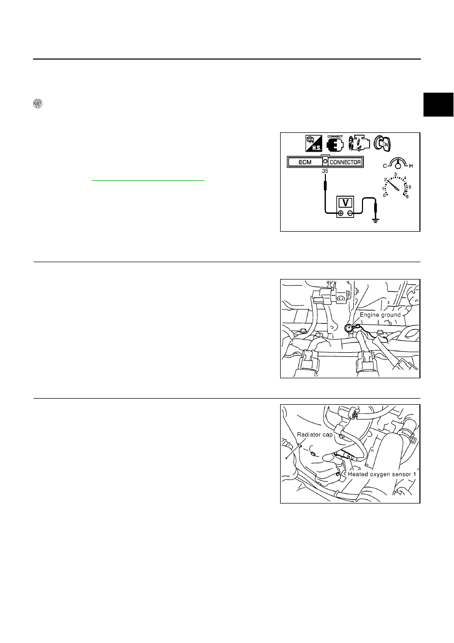
WITH GST
1.
Start engine and warm it up to normal operating temperature.
2.
Set voltmeter probes between ECM terminal 35 (HO2S1 signal) and engine ground.
3.
Check one of the following with engine speed held at 2,000 rpm
constant under no load.
–
The maximum voltage is over 0.6V at least one time.
–
The minimum voltage is over 0.1V at least one time.
4.
If NG, go to
EC-411, "Diagnostic Procedure"
.
Diagnostic Procedure
EBS00QPS
1.
RETIGHTEN GROUND SCREWS
1.
Turn ignition switch “OFF”.
2.
Loosen and retighten engine ground screws.
>> GO TO 2.
2.
RETIGHTEN HEATED OXYGEN SENSOR 1
Loosen and retighten heated oxygen sensor 1.
>> GO TO 3.
MBIB0018E
MBIB0095E
Tightening torque: 40 - 60 N·m (4.1 - 6.2 kg-m, 30 - 44 ft-lb)
MBIB0098E