Almera Tino V10 (2003 year). Manual - part 79
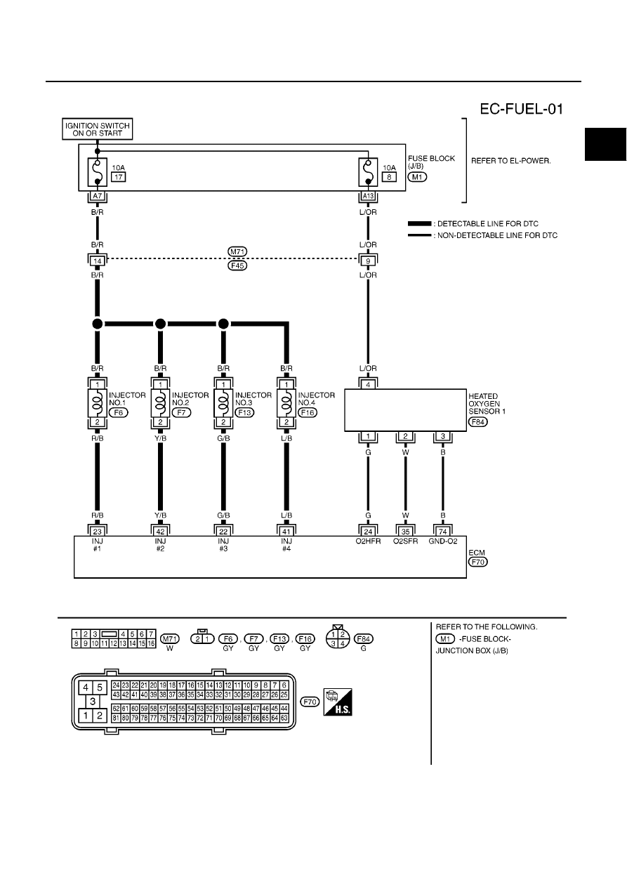
DTC P0171 FUEL INJECTION SYSTEM FUNCTION (M/T MODELS)
EC-283
[QG (WITH EURO-OBD)]
C
D
E
F
G
H
I
J
K
L
M
A
EC
Wiring Diagram
EBS00QLP
YEC449A
|
|
|
DTC P0171 FUEL INJECTION SYSTEM FUNCTION (M/T MODELS) EC-283 [QG (WITH EURO-OBD)] C D E F G H I J K L M A EC Wiring Diagram EBS00QLP YEC449A |