Almera Tino V10 (2003 year). Manual - part 49
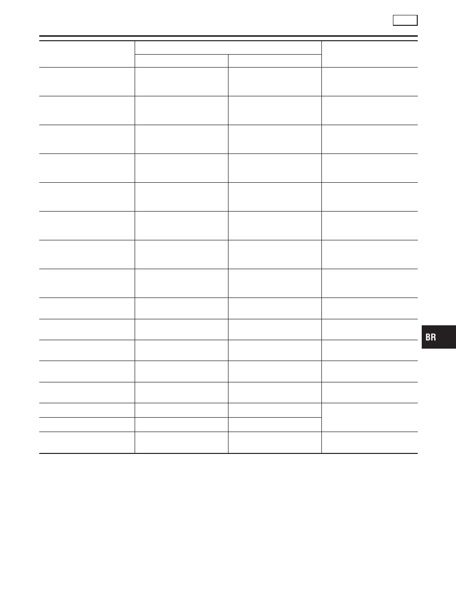
Item (Unit)
Monitor item selection
Remarks
Main item
Item menu selection
FR RH IN SOL
×
×
Operating condition (ON/OFF)
of rear RH ABS inlet solenoid
valve is displayed.
FR RH OUT SOL
×
×
Operating condition (ON/OFF)
of rear RH ABS outlet solenoid
valve is displayed.
FR LH IN SOL
×
×
Operating condition (ON/OFF)
of rear RH ABS inlet solenoid
valve is displayed.
FR LH OUT SOL (ON/OFF)
×
×
Operating condition (ON/OFF)
of rear RH ABS outlet solenoid
valve is displayed.
RR RH IN SOL (ON/OFF)
×
×
Operating condition (ON/OFF)
of rear RH ABS inlet solenoid
valve is displayed.
RR RH OUT SOL (ON/OFF)
×
×
Operating condition (ON/OFF)
of rear RH ABS outlet solenoid
valve is displayed.
RR LH IN SOL (ON/OFF)
×
×
Operating condition (ON/OFF)
of rear RH ABS inlet solenoid
valve is displayed.
RR LH OUT SOL (ON/OFF)
×
×
Operating condition (ON/OFF)
of rear RH ABS outlet solenoid
valve is displayed.
ACTUATOR RLY (ON/OFF)
×
×
Condition of ABS actuator
relay (ON/OFF) is displayed.
MOTOR RLY (ON/OFF)
×
×
Condition of ABS motor relay
(ON/OFF) is displayed.
WARNING LAMP (ON/OFF)
×
×
Indicates ABS warning lamp
operating condition
BATTERY VOLT
×
×
Indicates voltage supplied by
ABS actuator and electric unit
CAN COMM (OK/NG)
—
—
CAN communication signal
(OK/NG) status is displayed.
CAN CIRC 1 (OK/UNKWN)
—
—
CAN communication signal
(OK/UNKWN) status is dis-
played.
CAN CIRC 2 (OK/UNKWN)
—
—
Voltage
—
×
Displays values measured by
voltage probe
×
: Applicable
–: Not applicable
ACTIVE TEST
NLBR0210S04
Operation Procedure
NLBR0210S0401
CAUTION:
I
Do not perform active test wheel running.
I
Be sure completely bleed air from brake system.
I
Active test cannot be performed with ABS warning lamp
on.
1.
Connect CONSULT-II to data link connector and start engine.
GI
MA
EM
LC
EC
FE
CL
MT
AT
AX
SU
ST
RS
BT
HA
SC
EL
IDX
ON BOARD DIAGNOSTIC SYSTEM DESCRIPTION
ABS
CONSULT-II Functions (Cont’d)
BR-67